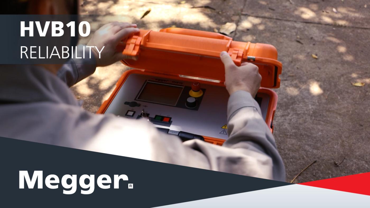
HVB10 high-voltage bridge for cable fault location
Measures resistance (not impedance) to help locate faults on long, cross‑bonded and submarine cables.
Choose fast standard mode for typical sheath faults, or high‑accuracy mode for high‑resistance and intermittent faults.
One instrument for 10 kV testing, pulsed DC/A‑frame pinpointing, and controlled burning to stabilise faults.
The integrated F-Ohm safety circuit helps support safer operation, while bipolar measurement reduces external influences, and the connection check helps identify wiring issues before testing begins. USB logging makes it easier to document results and maintain traceability.
About the product
HVB10 is a high-voltage measuring bridge for utilities and cable specialists who need reliable pre-location when reflection-based methods struggle – for example on very long HV/submarine cables, cross-bonded systems, or high-resistance faults.
What you can do with HVB10
- Test insulation and cable sheaths with up to 10 kV DC (negative polarity) to identify weak points early.
- Pre-locate difficult faults automatically using the voltage drop method with bipolar measurement, helping eliminate external influences such as thermo‑electric and galvanic effects.
- Pinpoint sheath faults using either pulsed DC for the step‑voltage method (with a suitable receiver) or a 3 / 4.8 Hz A‑frame signal.
- Burn faults (controlled) with selectable current limit and up to 200 mA continuous output current for short periods, to stabilise intermittent or “drying” faults before pre-location.
Designed for long, high-capacitance cables
The built-in discharge unit supports test objects up to 25 µF, with capacity checking to protect the instrument. Power is available from a wide‑range mains input (88–264 V, 50/60 Hz) or the integrated rechargeable battery for around 2 hours of operation (typical conditions).
Faster, safer field workflow
HVB10 uses Megger’s EasyGo operation with a rotary encoder and touch screen, detects incorrect hook‑up, and stores test/log data to USB for reporting and traceability.
FAQ / Frequently Asked Questions
When fault pre-location by reflection is unreliable – for example, on very long cables, cross‑bonded systems, or high‑resistance/intermittent faults, where resistance-based location is more dependable.
No. HVB10 uses one single HV connection cable, so you do not need two HV cables. For standard fault prelocation, the device is normally used with two healthy auxiliary conductors connected at the far end. If only one fault-free auxiliary conductor is available, prelocation is still possible, but this is a special case and accuracy may be reduced. No special auxiliary lead parameters need to be entered
Use pulsed DC output with the step‑voltage method (with a suitable receiver), or use the 3/4.8 Hz signal for A‑frame pinpointing.
Yes. The integrated rechargeable battery supports field operation; it can also be charged while you’re on the move from your vehicle’s 12/24 V DC.
Further reading and webinars
Troubleshooting
- Check that the HV interlock key switch is in the unlocked position and the emergency-off is released.
- Confirm the protective earth is connected to a suitable station earth. Poor earthing can prevent HV operation.
- Check the HV cable is correctly seated and locked.
- Recheck lead placement for the selected mode, and ensure good, clean contact surfaces.
- If connections are correct but the check still fails (e.g. very high cable capacitance, low-resistance faults, small cross-section), disable the connection check in System Settings and proceed carefully.
- Try both test voltages and observe if results change significantly; multiple faults can create averaged/false distances.
- If multiple faults are suspected, carefully increase voltage to ignite the most ‘ignitable’ fault, locate/repair, then repeat.
- Switch to mains supply where possible and allow the battery to charge.
- For long pinpointing sessions, plan around typical battery operating time and your output power settings.
Interpreting test results
Insulation/sheath test outcomes
HVB10 records voltage and leakage current during DC withstand tests. In practice, you will typically see one of three outcomes:
- Pass (stable current and voltage):[LW1.1] insulation/sheath condition appears healthy. Continue with normal maintenance intervals.
- Elevated leakage current: consider closer investigation or shorten the re-test interval, in line with your organisation’s limits.
- Breakdown(s)/flash-over: indicates a defect. Where possible, move straight to fault prelocation and then pinpointing.
Prelocation results
HVB10 automatically prelocates faults using the voltage drop method with bipolar measurements. Use:
- Standard mode for typical sheath faults (often faster).
- High accuracy mode for difficult, high‑resistance or intermittent faults.
Pinpointing and reporting
For sheath faults, pinpoint using pulsed DC (step-voltage method) or the 3/4.8 Hz A‑frame signal. If logging is enabled, export results to USB for reporting and archiving (e.g., in MeggerBook or MeggerBook Lite).
Software and firmware updates
Meggerbook
MeggerBook and MeggerBook Lite
MeggerBook & MeggerBook Lite Software
latest version
What’s new in version 4.4.0
Updates
- Incorrect reset of the propagation speed v/2 on the Settings page
- Incorrect behavior of the Settings page when the virtual keyboard is absent
- Crash when editing report templates
- Preview pages are displayed in letter format
- During an active search, entries that are not visible can be selected
- The cable description in the report does not display any special characters (including ü¼ö¶ä¤)
- In TDR analyses, the velocity is always given in v/2
Improvements
- Database version check
- Refresh on cable changes
- Phase-resolved tanDelta trend data in BA TanDelta MWT
- Improve handling of Winkis data (Sqlite2)
- Save import/export folder path in MeggerBook
- Update TanDelta standards
- Display GPS status on map
- Display the sleeve or cable type when hovering over the cable run
New Features
- Display TE measurements properly in the activity view in MeggerBook
- The radio options on the "Language settings" page are not working well
- Extremely large Megger-mcb files due to PDF reports made manageable
The setup file below is suitable for the installation of both MeggerBook (full version) and MeggerBook Lite (free limited version).
When started with after adding the electronic license key into the installed software, the software starts as MeggerBook full version which allows for easy and comprehensive data evaluation, data archiving, cable management and report creation. A personal quotation for a certain number of licenses can be requested here . The new electronic license key allows for 3 devices to have MeggerBook full version installed on them.
The dongle key licenses from older versions of MeggerBook are not supported with this newer version. Updated electronic license keys can be requested here for previous customers.
Without the required software license key the software starts as MeggerBook Lite which allows for seamless report creation and offers some of the features as the full version while limiting the data storage options as follows:
• Measurements, analyses and reports are not permanently stored in the database
• While cable import and storage are not limited, a maximum of 5 cables can be created using the cable editor of the Lite Edition
At this time, the software can handle the measurement and test data of the following Megger devices:
Test vans: Centrix 2.0, Primeon Centrix City, Compact City, R30 2.0, Variant
Test systems: VLF Sine 34 / 37 / 45 / 62, VLF CR 40/60, TDS 40/60, Easytest 20, MFM 10
TDRs: Teleflex VX(-P), Teleflex SX-1
Note for test systems VLF Sine Wave 45 and VLF Sine Wave 62:
Data of these test systems can only be imported into the software, if the test systems is equipped with firmware version 3.14 or higher. The latest firmware can be found here (VLF Sine Wave 45) and here (VLF Sine Wave 62).
FAQ / Frequently Asked Questions
Up to 25 µF. Do not exceed this limit.
Yes, for low-probability fault checks, you can bridge conductors, but the combined capacitance must remain within limits. If leakage is detected, test each conductor individually.
Enable logging in System Settings, insert a USB drive when prompted at the end of a test, and save the file for later review.
During automatic prelocation, the instrument completes the current sub-step before stopping. In an emergency, use the emergency-off, which immediately switches off HV and discharges the cable.