Development and field experience of turns ratio testing

Jialu Cheng - Application engineer
The transformer turns ratio (TTR) test is very important; it confirms that the transformer has the correct ratio of primary turns to secondary turns. Using this test correctly can help to identify shorted turns, open windings, incorrect winding connections and other faults inside transformers.
The principle of TTR is that an AC voltage is applied to the primary side of the transformer and the induced voltage at the secondary side is measured. For single phase transformers, the transformer voltage ratio, TVR, is equal to the transformer turns ratio, TTR: where, is the primary winding number of turns and is the secondary winding number of turns. The transformer nameplate ratio, TNR is determined by TTR and the vector group. The tester measures the voltage ratio TVR and then calculates TNR and TTR based on the winding connections. Therefore, information about the correct vector group should be available when performing the turns ratio testing.
However, tests in special applications, such as those involving phase shift transformers, can be difficult with single-phase instruments. These transformers usually have a phase shift of 30 ̊ ± 7.5 ̊. A new algorithm introduced in IEC 61378-1 Ed.2 proposes a solution to test phase-shift transformers with single-phase instruments. The test parameters and calculation methods are based on a geometrical and trigonometrical approach. Instruments in the latest Megger TTR series apply the algorithm. They are also able to detect the vector group of the tested object so the nameplate information is not necessity any more.
IEEE standard (C57.152) states that when the rated voltage is applied to one winding of a transformer, all other rated voltages at no load shall be correct within 0.5% of the nameplate readings. The deviation is calculated by:
Field experience has shown that shorted turn-to-turn fault might be difficult to identify if only referring to the ratio results. Figure 1 is the TTR test result for a transformer that tripped because of a turn-to-turn short circuit. The results look very good and no problem can be found. But the excitation current provided more information about the fault.
The best TTR testers have the ability to measure the excitation current during turns ratio testing. In this case, the excitation current of phase A reaches 257 mA when the test voltage goes to 100 V! This is the strong evidence indicating that there is something wrong with the transformer.
Figure 1. Turns ratio testing results from a transformer with 19 primary taps
It is also worth noting that results from hand held TTR testers sometimes show deviations larger than expected for instrument transformers. It is recommended to use testers with relatively higher test voltage such as 80 V for those high-ratio transformers. Because higher voltage improves the core excitation level as well as the measurement accuracy.
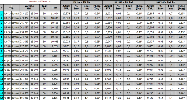
Figure 1. Turns ratio testing results from a transformer with 19 primary taps
Tags: primary, ratio, secondary, testing, transformer, TTR, turns


