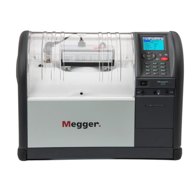
OTS PB and OTS AF series of insulating oil test sets
Suitable for field or laboratory use
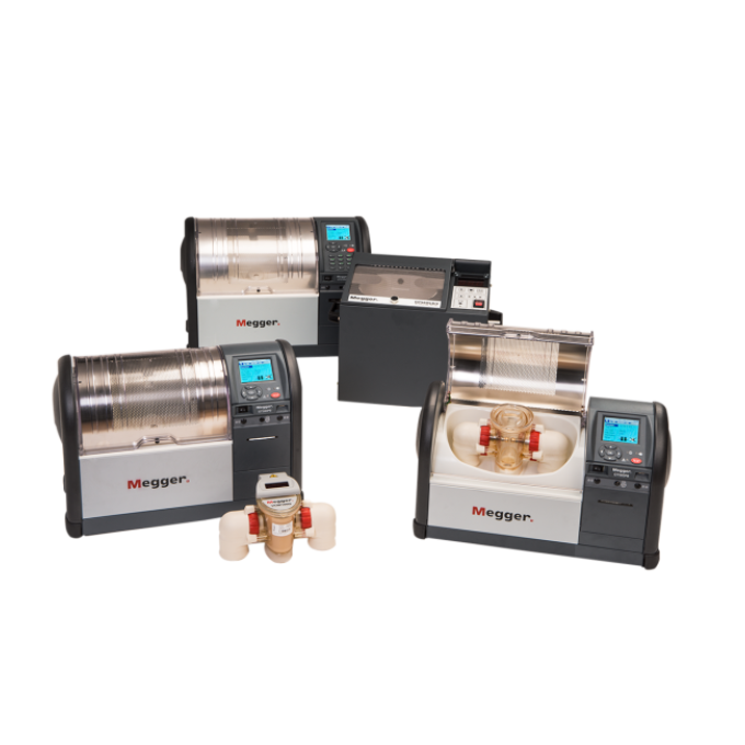
PB models are small and light, starting at 16.8 kg in weight for field use. The AF range has a larger test chamber for increased test capacity for lab use
Durable, convenient, and reusable
Test vessels are shatterproof, easy to clean, and reusable. This reduces waste whilst achieving repeatable results
Programmed with current test standards
All of the current test standards worldwide are pre-loaded in the instrument for convenient automatic operation
Eliminate accidental electrode movement
A convenient and precise thumbwheel adjustment for electrode spacing incorporates a locking mechanism that completely eliminates accidental electrode movement during testing
About the product
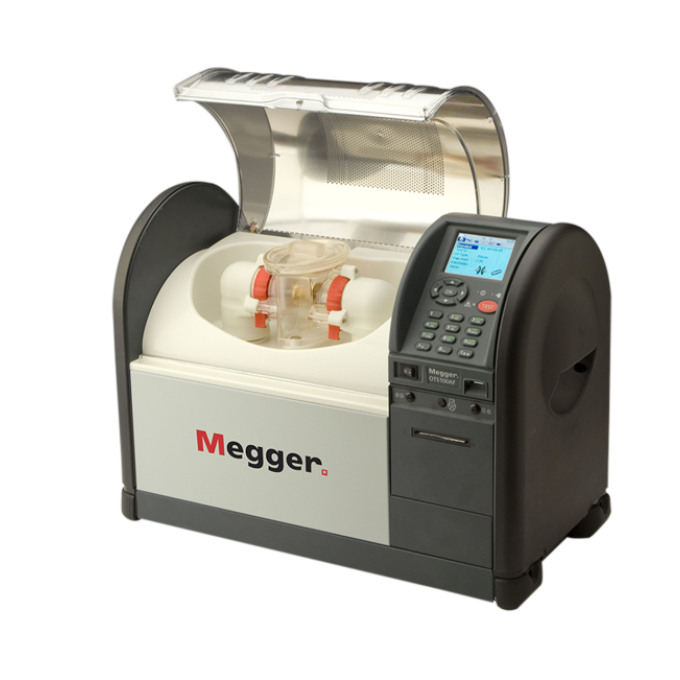
The OTS PB and OTS AF insulating oil test sets are a range of automatic oil test sets that perform accurate dielectric breakdown voltage tests on mineral, ester, and silicone insulating liquids. This critical test indicates the ability of a fluid to withstand electric stress. All models have precision, shatterproof test vessels that are easy to clean and provide repeatable results, whether used in the field or laboratory. They also have a transparent, shielded lid and a large test chamber, giving easy access to the test vessel and allowing you to see what is happening within it.
Test results are identified either by a serial number or asset ID and are time and date stamped. OTS units come with PowerDB Lite, Megger's asset and data management software, at no extra cost, giving you an excellent tool for downloading and printing results. The units have an internal printer so that you can have a hard copy of your results, if needed. In addition, the AF model includes a barcode scanner.
We have designed these test sets with your safety in mind. During a test, you can terminate the measurement at any time by pressing any button on the keyboard. Such a keyboard stroke will remove the high voltage immediately and abort the test. Additionally, the transparent lid provides ample visibility within the chamber yet is protected and electrically shielded by a screen with multiple links to the instrument's ground.
All existing test standards worldwide are pre-loaded in the instrument for convenient automatic operation. However, should a new test standard be accepted or a current standard amended, you can configure three custom tests to the new requirements. This flexibility enables you to continue testing for the short period over which Megger updates the test procedure files. New updated files are then downloaded by the user and installed into the test instrument via a USB drive.
OTS PB models
These 60 kV and 80 kV oil test sets are the smallest and the lightest on the market, with weights ranging from 16.8 kg to 20.8 kg, depending on the model configuration. These units can be mains powered or battery operated for additional flexibility in portable applications. All PBs are fitted with NiMH batteries and are also supplied with an internal 12 V DC charger and a vehicle adaptor cable as standard issue. The transport case and carry bag are optional accessories. The carry bag has pouches for the electrode accessory pack, leads, a quick user guide, and a paper roll.
OTS AF models
These 60 kV, 80 kV, and 100 kV models have a much larger test chamber for even easier access and cleaning, which is particularly useful in a lab environment. They are fitted with a 12-key alphanumeric keypad to facilitate the entry of test IDs, file names, and notes. Alpha characters are entered by repetitively pressing a key. The AF models also can use a USB barcode reader to scan oil sample barcode labels, which is ideal for better integration within a laboratory.
Technical specifications
- Test type
- Oil dielectric breakdown
Further reading and webinars
Troubleshooting
Check the gap between the electrodes and make sure the vessel is cleaned according to the standards.
Megger offers a voltage check metre that can be fitted to the instrument in place of the measuring vessel. Doing so allows you to compare the voltage shown on the check metre with that shown on the instrument display. Check meters are not sufficiently accurate to use as a calibration standard. Still, they provide an excellent way of detecting changes in instrument calibration. You should record the check meter readings each time you carry out a voltage check to identify changes quickly. If any significant change is detected, you should not use the instrument until you have returned it to Megger or an accredited service centre for servicing and recalibration.
Indicators that you need to send your OTS into Megger or to an accredited service centre for repair include your OTS not booting up or not building voltage.
Interpreting test results
There are several key factors to consider to carry out effective and reliable insulating oil dielectric breakdown testing. You’ll need to know that your results are valid, considering standards and their specific conditions that must be met. You also need to know if your insulating fluid meets manufacturing standards.
This extract of a chart comparing standards shows that each standard specifies different conditions that must be met if the test results are to be accepted as valid. You can find the full chart in our ‘Guide to insulating oil dielectric breakdown testing’.
| Standards | ASTM D1816 | ASTM D877 | IEC 60156 | |
|---|---|---|---|---|
| Procedure A | Procedure B | |||
| Valid test conditions | If breakdown does not Tests must be repeated if range of BD voltages recorded | Tests must be repeated if the range of BD voltages recorded are more than 92 % of mean. If the range of 10 BD voltages is more than 151 % investigate why. | Expected range of standard deviation/mean ratio as a function of the mean provided as a chart. | |
Mean is the average of the breakdown values recorded in the test sequence. For example, if the breakdown values are 33 kV, 37 kV, 32 kV, 35 kV, 38 kV, and 34 kV, the mean value would be the total of these results – 209 – divided by the number of results – 6 – which gives a mean value of 209/6 = 34.83 kV. (Note that in this example, there are six results as required by the IEC standard. The ASTM standards require either five or ten results.)
Range of breakdown voltage is referred to in the ASTM standards. For example, D877 specifies that the test sequence must be repeated if the range of breakdown voltages recorded is more than 92 % of their mean value. Two examples will make this easier to understand.
In the first example, the breakdown voltages recorded are 43, 45, 52, 40, and 38 kV. The lowest value is 40 kV and the highest is 52 kV, so the range is 12 kV. The mean of the recorded values is 43.6 kV, so the range is only 12/43.6 x 100 % = 27.5 % of the mean value. These test results are, therefore, valid.
In the second example, the breakdown voltages recorded are 33, 45, 52, 18, and 20 kV. The lowest value is 18 kV and the highest is 52 kV, so the range is 34 kV. The mean of the recorded values is 33.6 kV, so the range is 34/33.6 x 100 % = 101 %. This is above the 92 % limit, which means that the test must be repeated.
Standard deviation: IEC 60156, there is a graphical representation of standard deviation – otherwise known as the coefficient of variation – versus the mean breakdown voltage. Calculation of the mean has already been covered, but what about the standard deviation? IEC 60156 does not explain how to calculate this. The procedure, however, is to calculate the difference between each of the six test results and the mean value of those test results, then square each of the differences and add them together. Divide the figure obtained by 2, and then take the square root. The final answer is the standard deviation for the set of test results.
IEC 60156 states that, for the test results to be considered valid, the following procedure must be followed:
- Perform six tests
- Calculate the mean of the results
- Calculate the standard deviation (see above)
- Divide the standard deviation by the average value, noting that scatter is expected and acceptable (see the chart at the end of IEC 60156)
- If the value is acceptable, conclude testing
- If not, perform six more tests
- Repeat the calculations using all 12 results
An insulating fluid manufacturer normally quotes typical new and in-service fluid breakdown values in its data sheets. In addition, the test standards refer to oil condition standards that provide guidance about the acceptability of results.
D877 is usually only recommended to accept new oil from a supplier. However, some oil testing laboratories still recommend its use for specific in-service applications. In these cases, a breakdown voltage of 30 kV or more is usually considered acceptable, with values below 25 kV unacceptable. Values between 25 and 30 kV are considered questionable. For new oil, a minimum value of 30 kV is normally specified.
| Oil type | New oil |
|---|---|
| Mineral oil | 45 kV |
| Silicone oil | 40 kV |
| HMWM | 52 kV |
| Synthetic ester | 43 kV |
| Natural ester | 56 kV |
D1816 is more widely used and is accepted by the IEEE as the test method to be used for dielectric breakdown testing for the acceptance and maintenance of insulating oil. The IEEE C57.106 standard incorporates the D1816 limits – which are shown below – for new and in-service oil. Note that the values provided in this table are for mineral oil.
IEEE C57.106-2006
IEEE Guide for acceptance and maintenance of insulating oil in equipment
| Applications | Voltages class/group | D1816 (1 mm gap) | D1816 (2 mm gap) |
|---|---|---|---|
| New mineral insulating oil as received from supplier | Not specified | >20 kV | >35 kV |
| New mineral insulating oil received in new equipment, prior to energisation | ≤69 kV | >25 kV | >45 kV |
| 69 to 230 kV | >30 kV | >52 kV | |
| New mineral insulating oil - processed from equipment, prior to energisation | 230 to 345 kV | >32 kV | >55 kV |
| ≥345 kV | >35 kV | >60 kV | |
| Service-aged insulating oil - for continued use (Group 1) | ≥69 kV | >23 kV | >40 kV |
| 69 to 230 kV | >28 kV | >47 kV | |
| ≥230 kV | >30 kV | >50 kV | |
| Shipments if new mineral insulating oils, oil circuit breaker (OCB) | OCB | >20 kV | >30 kV |
| New OCB insulating oil - after processing, prior to energisation | OCB | >30 kV | >60 kV |
| Service-aged OCB insulating oil - for continued use | OCB | >20 kV | >27 kV |
| New mineral oil for load tap changer (LTC), prior to energisation | LTC | >35 kV | >55 kV |
| Service-aged LTC insulating oil - for continued use | LTC - Neutral | >20 kV | >27 kV |
| LTC - ≤69 kV | >25 kV | >35 kV | |
| LTC - >69 kV | >28 kV | >45 kV |
IEC 60156 uses acceptance values that are contained in two further standards: IEC 60296 and IEC 60422.
IEC 60296, fluids for electrotechnical applications: Unused mineral insulating oils for transformers and switchgear. As its title indicates, this standard applies only to new, unused oil as received from the manufacturer, which must have a dielectric breakdown voltage of 30 kV or more, determined using the IEC 60156 test method. Oil that has been vacuum filtered in a laboratory must have a minimum dielectric breakdown voltage of 70 kV.
IEC 60422, mineral insulating oils in electrical equipment: Supervision and maintenance guide. This standard prescribes acceptable dielectric breakdown values for new oil (after filling but before energising) and for in-service oil. The values are:
| Equipment voltage | Dielectric BD voltage |
|---|---|
| ≥72.5 kV | >55 kV |
| >72.5 kV ≤170 kV | >60 kV |
| >270 kV | >60 kV |
| Equipment voltage | Dielectric BD voltage | ||
|---|---|---|---|
| Good | Fair | Poor | |
| ≥72.5 kV | >40 kV | 30 - 40 kV | >30 kV |
| >72.5 kV ≤170 kV | >50 kV | 40 - 50 kV | >30 kV |
| >270 kV | >60 kV | 50 - 60 kV | >50 kV |
The IEC recommends that if values are in the ‘fair’ range, testing should be performed more frequently, and that the test results should be cross checked with other testing methods. If the test results are in the ‘poor’ range, the oil must be brought back into a good state by reconditioning. This might, for example, involve filtering and drying the oil.
User guides and documents
Software and firmware updates
OTS Test Standards
The attached file will update all the test standards of your OTS to the latest versions. Do not change the file name or it will not work. Please follow the instructions below:
- Extract the attached file (stdSeqs.db) to a USB memory stick
- Insert the memory stick into the Type A USB port on the front panel of the OTS (or the Type A USB port on the rear of the OTS)
- On the OTS, navigate to the Tools menu with the Hammer & Wrench symbol
- Scroll down and select Manage test standards
- On the next screen select Update Standards (USB) and the instrument will upload the new file from the USB stick.
- The instrument will now have the latest standards installed ready to use.
For Older OTS (Firmware version 1.15) use "OTS-Test-Standards-V0-10.zip". For updated OTS (Firmware version 3.xxx) use "OTS-Test-Standards-V0-30.zip"
IMPORTANT NOTE:
- OTS-Test-Standards-V0-30.zip is not compatible with OTS Firmware version 1.15
- OTS-Test-Standards-V0-10.zip is not compatible with OTS Firmware version 3.xxx
