ICMsystem versatile partial discharge measurement system
Highest degree of versatility
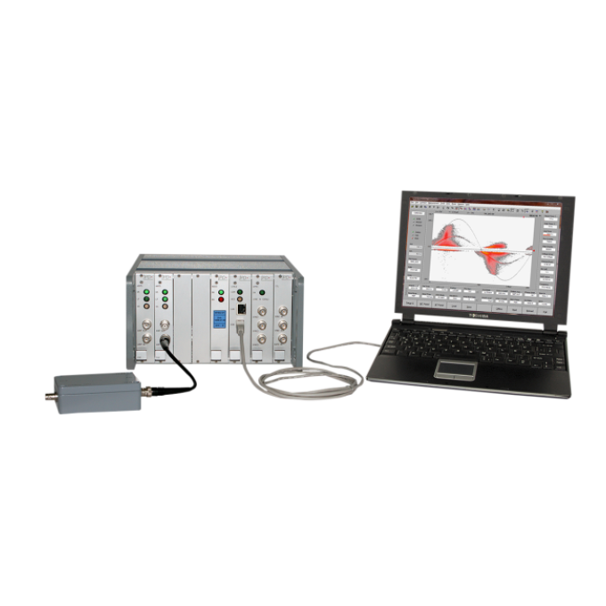
The key to the versatility of the ICMsystem is its modular design. The ICMsystem can be matched up with a variety of special accessories that adapt it to virtually any high -voltage (HV) PD testing environment.
One instrument for a wide range of high voltage assets
The ICMsystem can be used on transformers, rotating machines, gas-insulated switchgears (GIS), air-insulated switchgears (AIS), high voltage (HV) and extra high voltage (EHV) cables as well as HV components, such as bushings, insulators, and capacitors.
PD and RIV acceptance tests according to international standards
Perform factory acceptance tests that fully comply to the IEC 60270.
Parallel measurement and recording of several PD sources
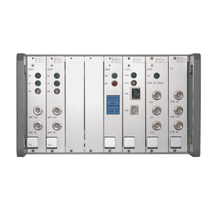
The ICMsystem can be equipped with up to ten parallel real-time measurement channels to test complex assets.


About the product
Power Diagnostix’s ICMsystem is a versatile partial discharge (PD) measurement system. This universal PD device can be used by adjusting versatile features and accessories to fit your specific testing purpose. It has the highest grade of modularity and versatility making it ideal for, laboratory tasks (QAQC) and on-site testing (on-line and off-line) for all your assets.
As a multi-purpose PD measurement instrument, the ICMsystem offers the following features and options:
- PD spectrum analysis
- High voltage measurement (HVM)
- Synchronisation frequency from VLF to 510 Hz
- DC measurement mode
- DAkkS calibrated voltage measurement
- Acoustic fault localisation
- PD fault localisation on cables
- Effective noise gating for blocking phase-stable or phase-independent noises
- Radio influence voltage (RIV) measurement
- High -resolution PD patterns
Assorted coupling devices, including quadrupoles, coupling capacitors, and current transformers, are available to sense the PD signal in the object under test. The instrument provides effective noise gating that blocks phase-stable noise as well as noise independent of the applied voltage cycle, allowing the ICMsystem to be used in noisy environments without losing significant PD data. Appropriate selection of a preamplifier can assist further in achieving a high signal-to-noise ratio.
The ICMsystem is fully computer controlled. All controls and displays are accessible on the screen of a PC via a graphical interface;, a so-called ‘virtual instrument’.
FAQ / Frequently Asked Questions
As a multi-purpose instrument, the ICMsystem can perform a range of different measurements and tests, such as• Partial discharge measurements • Partial discharge fault location on cables • Acoustic fault location • High voltage measurements • Radio interference voltage (RIV) measurements
The IEC 60270 standard covers the measurement of partial discharges occurring in electrical equipment, components, or insulation systems when tested with AC voltages up to 400 Hz or with DC voltage. It specifies requirements for the measurement equipment and for calibrators that should be used for measuring. Additionally, it defines three possible measurement setups to ensure reproducible and comparable PD measurement results.Power Diagnostix’s ICMsystem meets all the requirements of the standard and thus guarantees highly accurate and reliable measurement results.
Observing the frequency spectrum of a harshly disturbed partial discharge signal enables you to select frequency bands with fewer disturbances. Using such a selected frequency for a partial discharge acquisition, gives a largely improved signal-to-noise ratio resulting in a clear pattern acquisition. The combination of spectrum analyser and PD detector within one instrument opens a broad field of new possibilities when analysing isolation defects, even in noisy environments.
An effective noise reduction is required in case measurements are taken in an environment with high frequency (HF) disturbance, such as a frequency converter switching pulses, corona discharge, or a thyristor firing. This is because these disturbances can hamper partial discharge detection.The ICMsystem uses a gating signal picked up by a disturbance antenna, or a high frequency current transformer, which is used to blind out the disturbances during the measurement.General background noise can be handled by setting a low level discriminator (LLD) in the control software.
Further reading and webinars
Related products
Troubleshooting
The two micro controllers of the acquisition unit build up an internal communication upon start up. They check different registers, the controller periphery, their internal communication, and finally, determine if all modules are in place. With this boot sequence successfully passed, you will hear a single ‘beep’ sound, and the OK LED of the AMP5 module will be lit. In case of severe malfunction, this process will not be completed. When peripheral failures are detected, several beep sounds will indicate the detected defect. In both cases, the acquisition unit needs to be returned to the Power Diagnostix factory.
On PCs running Windows 10 with the Creator'’s Update of (2017), the ICMsystem application window may appear very small on high resolution monitors. To enlarge the display size of the software, please take the following steps:
1. Right-click on the application short cut on the desktop.
2. Choose “'Properties'” from the context menu. This will open the “Properties” window.
3. On the 'Compatibility'” tab, enable 'Override high DPI scaling behaviour”' and set 'Scaling performed by”' to 'System”'.
4. If you have administrator rights, you can change the settings for all users by clicking the corresponding button.
5. Approve the change by pressing the “OK” button.
Upon start -up, the ICMsystem software checks for a connected instrument automatically. With the instrument found, the acquisition unit beeps, and the communication starts immediately as described with the software section of the ICMsystem user guide. In case the communication could not be established, try to use the GPIB or USB interface of the computer with another application. Check the GPIB/USB cable and connectors or try another GPIB/USB interface. You may also try to connect by another computer. Additionally, the serial communication may be tested. Use the serial cable supplied and set the software to check the serial port used in the menu “Options” > “Port”. In case the communication could not be established, and the instrument was identified as the cause, it needs to be sent to Power Diagnostix for further investigations and/or repair.
Verify the USB driver is installed. To do this, check the section “Ports” of the Windows Device Manager. You should see an entry “CP210x” or “Silicon Labs CP...” If there is no entry within the “Ports” section, you will most likely find the device under “Unknown/Other devices” with no driver installed.
Right- click on the device entry and chose “Update driver software”. Install the software manually and choose the option “Let me pick from a list of device drivers on my computer" and “Have disk". Then, go to the software installation folder and open the subfolder USB_Driver\CP210X\SLabBridge. Select the “.inf” file there. Depending on the version of your operating system, you may have to install a second part of the driver. In this case, go to the section “Universal Serial Bus controllers” in the Windows Device Manager and locate the “CP210x” device. Repeat the previous steps with the subfolder USB_Driver\CP210X\SLabBus. After the successful driver installation, you should have an entry within the “Ports” section of the Device Manager: Now you can activate this COM port in the ICMsystem software preferences.
User guides and documents
FAQ / Frequently Asked Questions
Depending on the level, nature, and source of the disturbing signals, the ICMsystem offers different options for noise handling. A noise level that is stable over the whole phase can be removed from the PD pattern by the low level discriminator (LLD) function. If the disturbance source is known, such as with the switching of a relay or a thyristor firing, the ICMsystem can be supplied with a TTL signal to blind out the PD measurement path. For the time the TTL input is (logically) high, no PD signal is recorded. In case the ICMsystem is used for PD measurements in an environment with high frequency (HF) disturbance, such as radar signals, corona discharge, or thyristor firing, it can be connected to an external noise sensor that picks up the disturbance signal. This signal is used to effectively reduce noise by blending out impulse noise
If the ICMsystem is equipped with at least one measuring module with the spectrum option, the instrument can be used as spectrum analyser and RIV meter. This combination enables you to perform PD measurements even with large background noise, e.g., in non-shielded test areas. The necessary RIV calibration can be performed according to NEMA 107 or CISPR 18-2, the ICMsystem can cope with both methods. A
The ICMsystem does not need any calibration, nor does it require any maintenance on a regular basis, as the partial dischargePD measurement is a relative measurement that is calibrated with a reference source prior to a measurement being taken. The calibration impulse generator as the reference source, however, should be calibrated on an annual basis to ensure that its output signal remains within the recommended boundaries.
The position of a preamplifier should be close to the coupling unit, so short BNC cables are recommended for this connection. Longer cables can be used for the connection of the preamplifier and the ICMsystem.
With the amendment of the IEC 60270 from 2015, all nine available AMP filter combinations of the ICMsystem are compliant with the IEC 60270.
Power Diagnostix offers a broad range of PD sensors, coupling, and signal conditioning units, as well as cables and other accessories, to cover virtually any high voltage testing situation with the ICMsystem.Please refer to Power Diagnostix’s accessories catalogue for further information.


