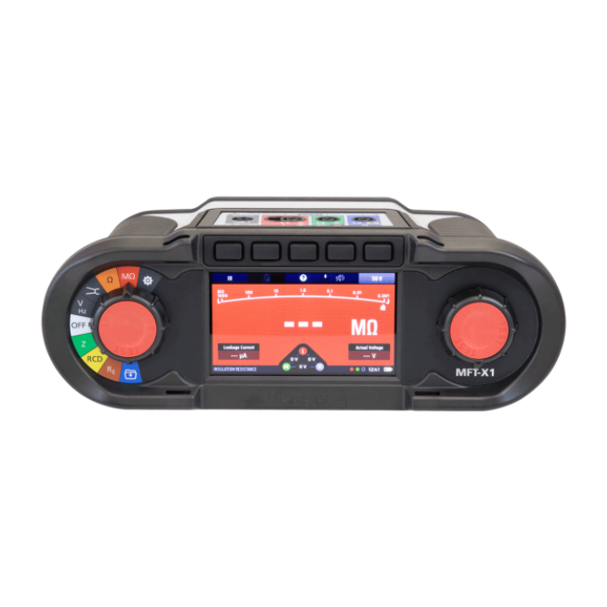
MFT-X1 Multifunction tester
Patented Confidence Meter™ for True Loop™ testing
Eliminates noise interference that produces inconsistence and instability of results, even close to source of supply, while reducing test time to as little as 7 seconds.
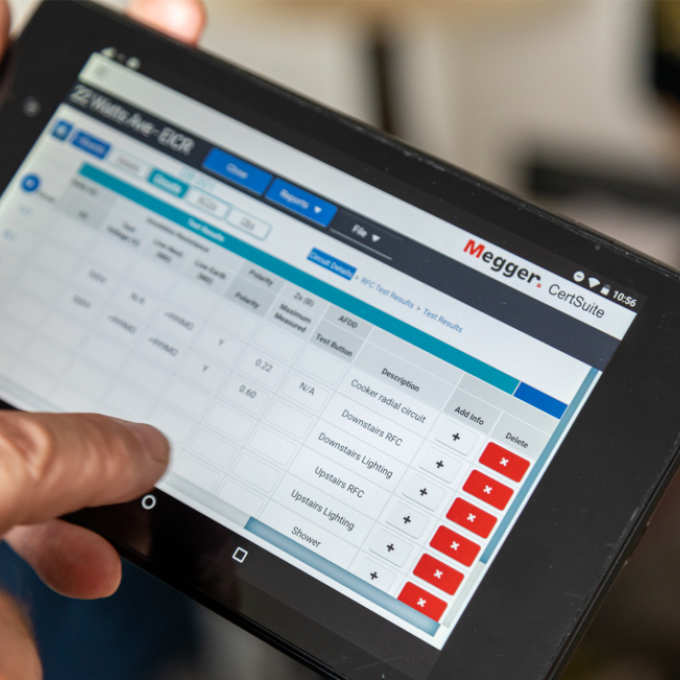
Easy certificate generation and reporting
Save yourself hours of operational work by combining the MFT-X1 with Certsuite™, which makes reporting and certificating whilst on the job a breeze! Test results can be transferred directly to any test certificate or report via the CertSuite™ App on a mobile device.
User upgradeable operating system
Testing capabilities of the Multifunction Tester can be readily kept in sync with changes in requirements from Standards agencies, local authorities, or any other agency overseeing building safety and operation. Using a standard microSD card, you will be able to remotely upgrade firmware and other features without having to purchase a new unit .
Intuitive interface for ease of use
Enhancing the colour coded test selection rotary dial, range selection is now replicated on the instrument screen, ensuring easy use in poor lighting environments.


About the product
MFT-X1 Multifunction Tester combines all the basic building-wiring installation, maintenance, and troubleshooting tests into a single light, portable, and user-friendly test instrument. While comparatively easy to perform, the tests are nonetheless of high accuracy, resolution, and reliability, in accordance with Megger’s long-established quality standards.
Trademarked Confidence Meter eliminates noise effects on loop tests. Results storage and downloading with upgradeable operating system keeps results up to date with changing standards.
Colour display minimises operator error.
Ideal for Photovoltaic (PV), Electric Vehicle (EV) Charge Point Testing, and RCD installation and maintenance.
FAQ / Frequently Asked Questions
The MFT-X1 is firmware upgradeable, so you can update the functionality with the latest functions, features and changes to testing standards as soon as Megger release them, free of charge.
The instrument is shipped with a production calibration certificate that is traceable to national standards.
Yes, but this must be requested when the instrument is being purchased, as we need to know the users details.
Yes. The instrument is approved to IP54.
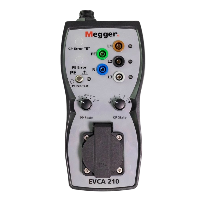
The MFT-X1 is supplied with a wide range of test leads for most applications, but for testing EV car chargers you will require the Megger EVCA adaptor. For earth resistance testing using the 3 wire ART method you will require the additional MCC1010 earth clamp. For the Stakeless earth testing you will require the MVC1010 clamp and the MCC1010 clamp.
Absolutely. It can be upgraded with additional test methods, features and firmware updates using the file provided on this page.
Further reading and webinars
Troubleshooting
This is most likely caused by a flat battery, battery insertion incomplete, or contamination of the battery pack terminals.
Connect the battery to the charger and ensure the charger light is green. The charger will show a red light if the battery needs charging. Ensure the battery is properly inserted and both the catches are engaged.
Check there is no contamination on the battery pack terminals. Is present, clean with isopropyl alcohol (IPA).
If the battery pack is a secondary pack (not originally bought with the instrument) ensure there is only one o-ring seal. Additional battery packs are sold with a seal but if one is already fitted to the instrument there are too many seals and the battery will not insert into the case fully.
Live circuit measurements such as loop impedance and RCD place a load on the live circuit . Lack of a live voltage when the test button is pressed will prevent the test from running
A PE Warning appears if the instrument is connected to a live circuit but it cannot detect a safe earth connection. The warning will always appear in these circumstances, but the inhibit of testing can be disabled in settings.
The warning is activated when the user touches the test button.
Interpreting test results
Resistance of the test leads – These should have their resistance nulled in the instrument so that measuring a short circuit displays zero Ωs. Typical test lead resistance will be around 0.035 Ω per lead. Failure to null this resistance can add significant errors at low resistances, especially below 1 Ω.
Fused Leads – These can also add additional fuse resistance. A 500mA fuse (as recommended by GS38) can add an additional 0.75 Ωs of resistance per lead.
Contact resistance – This will depend on the condition of the probe tip and that of the material to which they are applied. 0.04 Ωs in not uncommon and significantly higher values can be present. This can also apply to crocodile clips.
Crocodile clips – Due to the hinge mechanism within a crocodile clip, one side of a clip has a lower resistance than the other. The moving half having a higher resistance than the fixed half. Lead sets that are nulled prior to use may still induce errors if the croc clips were not nulled with their fixed halves joined together. Typical error can be around 0.03 Ω
Ambient temperature – Although this does influence the values reported, the changes in temperature are less significant than those detailed above. Compensation for temperature is well defined in electrical installation guidance documents and standards.
Presence of supply voltage – On continuity measurement a small voltage across the measurement terminals can significantly affect the measurement. A continuity test typically uses 4 V DC to 5 V DC to make its measurement. A voltage on the circuit of only 2 V AC or DC can significantly affect the measurement.
Electrical noise – Changes in the mains voltage or shape of the AC waveform during the test can create significant variation in the reported loop impedance. The more electrical noise on the circuit, the more variation in the results.
Load switching, harmonics, higher frequency noise all affect the measurement.
Micro-generation
Micro-generation, especially domestic solar power is a significant cause for variation in loop impedance, especially where load management is employed to divert power to internal loads rather than exporting to the grid.
RCD uplift
The RCD or RCBO can itself significantly affect the loop result during a non-trip test. The cause is the coils in the Phase and Neutral RCD providing the leakage sense. Uplift can be as high as 1 Ω but is more typically around 0.3 Ω to 0.5 Ω.
Proximity of a transformer – Continuity testers and Loop impedance testers tend to measure only the loop resistance of a circuit, rather than including the reactance (principally inductance) and calculating the true impedance of a circuit. Where the measurement is reasonably far away from a transformer, the most significant part of the measurement will be resistive, and errors are very small. Eg R = 0.3 Ω Xl = 0.01 Ω
Close to a transformer, the reactive component could be much higher compared to the resistance of the circuit, eg R = 0.006 Ω Xl = 0.025 Ω.
Most loop impedance testers struggle to measure this Reactance. Consequently the loop impedance and calculated fault current is based on the resistance of 0.003 Ωs and not on reactance of 0.025 Ωs. Loop impedance testers frequently measure <0.01 Ωs when the impedance is higher.
Using those figures above, at 230Vac the fault currant would be displayed on an instrument as:
Resistance of 0.006 Ωs 230 / 0.006 = 38.2KVA
Reactance of 0.025 Ωs 230 / 0.025 = 9.2KVA
The range of an instrument is simply the minimum and maximum values the instrument is capable of measuring in any particular measurement mode.
Overall range is constrained by the electrical capabilities of the instrument. Displayed range is defined by the display readout limitations, or digits.
An instrument that has '8888' as the digital readout may display 0.001 V on its minimum range, right up to 9999 V on its maximum range. Typically the range is adjusted to best fit the value being measured.
For the example above, the instrument could measure 0.025 V, but this range would only go to 9.999 V. After this the range would change to 10.00 V and now measure up to 99.99 V before changing to 100.0 V.
The right hand figure in each of these ranges denotes the resolution of the range.
Likewise the instrument cannot display 1.087338 V, as the limitations of the display only allow for 4 digits. Consequently the instrument would likely display 1.087 V, rounding up or down the last digit.
In reality the electronics are usually designed to manage measurements in the range that match the display. For example, an instrument with electronics that can measure to a resolution of 1 uV at 10 V is pointless if the display is limited to 4 digits. It is also a gross waste of money.
For the example above, the instrument could measure 0.025 V, but this range would only go to 9.999 V. After this the range would change to 10.00 V and now measure up to 99.99 V before changing to 100.0 V.
No instrument can provide perfect measurements in all conditions. Therefore an instrument declares an accuracy within which the instrument should perform for any measured value.
Accuracy figures are usually given as a percentage, followed by a number of digits. It typically looks like this example:
Accuracy = ± 5% ± 2d
The percentage is simply the amount the displayed value can deviate from the real value, as a percentage.
The ± 2d (or 2 digits) means how much the least significant number in the display an also vary. This depends on the resolution of the instrument and range selected.
So putting this together, measuring a voltage of 100 V on an instrument with a display that shows 100.0 V with an accuracy of ± 5% ± 2d could give a range of values as below:
From: 100.0 V less 5% = 95V Less 2 digits = 0.2 V = 94.8V
To: 100.0 V plus 5% = 105% Plus 2 digits = 0.2 V = 105.2V
Total range of variation is 10.4%
So in this case the percentage has a much bigger effect than the digits
However a small value, say 0.5 V, is affected by the digits far more than the percentage, as below:
From: 0.5 V less 5% = 0.025 V Less 2 digits = -0.2 V = 0.275V rounded to 0.27 V
To: 0.5 V plus 5% = 0.525V Plus 2 digits = +0.2 V = 0.725 V rounded to 0.73 V
Total range of variation is 92%
So it is very important to note that on very low values the number of digits in the accuracy statement can have significantly more effect than the percentage accuracy.
On an analogue display the situation is slightly different. Accuracy is usually stated as a percentage of full range. So, where an instrument has a range of up to 100V, a 1% accuracy would be equal 1V.
In this case the accuracy is stated as 1% of Full Range.
User guides and documents
Software and firmware updates
MFT-X1 Firmware
You can update the MFT-X1 when a new firmware release is available. The firmware releases are listed below with date released and summary of additional features:
Check the firmware revision of your MFT-X1 by selecting the "Settings" mode on the instrument and using the right arrow button to select "INST". The GUI and measurement versions are displayed. If a more recent firmware revision is available on this page, it can be downloaded to a microSD card as below.
To update your instrument operating system:
The update process installs the new OS from a microSD card. It is important to use a blank microSD card for this purpose. The microSD card MUST be removed from the instrument after the update has been completed, or the instrument will try to install the update each time it is switched on.
NOTE: Minimum recommended microSD card size is 4 GB and the maximum card size is 32 GB. The card must be formatted to the FAT32 format.
Download the latest operating system onto microSD card
1. Download the file from the link below.
2. Locate the MFT-X1 update ZIP file.
3. Unzip this file to your microSD card. It contains the instructions for updating the operating system and the required xxx.BIN file.
4. Check the version on the microSD card and verify the new file is a later revision than the one installed on the MFT-X1. Check Settings > INST > GUI Version.
5. Ensure the instrument is switched OFF and disconnect the test leads from the instrument.
6. Remove the battery pack and unscrew the fuse cover.
7. Fit the microSD card with the .BIN file into the microSD slot. (See user guide for guidance)
8. Replace the fuse cover and battery.
9. Switch the MFT-X1 to any range. The display will acknowledge the .BIN file is present.
10. Press the "Test" button. The instrument will now run 4 update steps.
11. At the end of a successful update the MFT-X1 will ask to be switched OFF.
12. Switch OFF the instrument and remove the microSD card. This is IMPORTANT. If left in the instrument will run another installation.
13. Replace fuse cover and battery pack. The instrument can now be used for testing.
It is very rare for the MFT-X1 to fail to update. In case of failure, refer to the user guide for possible errors during the update process.
MFT-X1 Firmware update
latest version
Release features:
- 3P ART and Stakeless Earth testing now available
- AA Alkaline battery pack now supported (available as an optional accessory - Part No: 1013-452)
- Continuity beep on completion – now beeps when continuity has a stable answer
MFT-X1 Firmware update (previous version)
Date: 07-09-2023
Release features:
- French language option available from the Instrument option in Settings
- Spanish language option available from the Instrument option in Settings
- Audible warning to the PE warning flag
- Removal of the CAL date from settings screen
FAQ / Frequently Asked Questions
There are serious inefficiencies and insecurities of storing test results within an instrument, which can result in a loss of days or weeks of work if the instrument is broken or stolen. The MFT-X1 is designed to send test results to a certification software package on the cloud. This allows results to entered instantly into a certificate and simultaneously worked on by multiple people and office staff if necessary. It is also fully secure and backed up, so it is not possible to lose test results.
It is a complex software algorithm, but essentially the Confidence meter is the engine of the loop test functions. It monitors all the sampled results during a loop test and where it sees results which it believes are incorrect, discards them, significantly improving the accuracy and repeatability of the final result.
This shows the progress of the loop impedance test. IT gradually closes to a centre dot when the instrument has collected enough data to be “confident” the result is accurate.
Yes, it couldn’t be easier. Just transfer the latest ZIP file from the Megger website to a microSD card, unzip it, plug it into the MFT-X1 and the rest is fully automatic.
Any approved calibration house or mobile service can calibrate the MFT-X1. The instruments are very stable, so they generally just check all measurements are working within their declared accuracies and provide a certificate.
Absolutely. It is fully traceable to national standards and has the calibration equipment details. It is produced when the instrument completes final testing in production, so is a perfect record of the instruments performance when it leaves the Megger factory in Dover.


