Discontinued
BGFT battery ground fault tracer
Operates in high electrical noise environment
Effective in high electrical noise environments as the strength of the test signal can be adjusted
Dual range supplies the required power and safety
Provides added safety in the low range, while the high range offers the ability to locate high impedance faults
Simplifies fault tracing
By identifying fault characteristic (resistive and capacitive) magnitudes


About the product
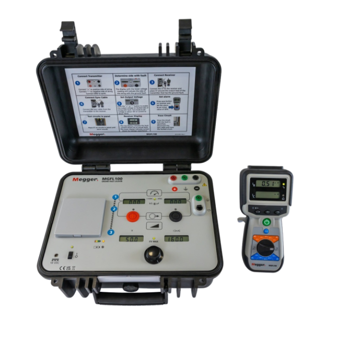
Suggested replacement for this discontinued product is the MGFL100
The BGFT battery ground fault tracer is a dual range, economical, easy-to-use instrument that identifies, traces and locates ground faults in ungrounded DC systems. It’s particularly effective in environments with high electrical noise as the strength of the test signal can be adjusted.
The BGFT comes with a dual range (high/low power switch), providing you with the ability to locate high impedance faults with the switch in the 50 V range, and providing added safety in the 15 V range.
The instrument also makes fault location quick as it eliminates trial-and-error procedures and can locate faults while the system is still energised. As such, it is particularly useful in any industry where the supply of power for operating measurement, communication and control equipment is critical.
Technical specifications
- Power source
- Mains
- Test method
- Battery ground fault tracing
Further reading and webinars
Related products
Troubleshooting
Often, an earth/ground fault will be solely resistive and reasonably easy to trace and find. Occasionally, there is a phantom short due to capacitance, which needs to be compensated for with a wheatstone bridge before tracing can ensue. There is information in the user guide and an operational guide available that further details this process. This document is helpful as a refresher course if you last went through this process a while ago. Additionally, Megger has an optional simulator available for purchase (BGFS) that is helpful for training or providing a refresher before chasing down an actual fault.
Check the fuses protecting the AC input circuitry. To check and/or replace these fuses, perform the following steps:
- Turn the “Voltage control” fully anti-clockwise.
- Set the “Output voltage” switch to “Disconnect”.
- Remove all AC power to the transmitter by setting the power on/off switch to 0. Disconnect the AC line cord.
- Using a small, flathead screwdriver, insert the tip into the slot located at the top of the AC power entrance module J1. The front face of the module will swing outward.
- Remove the fuse cartridges located within the module and marked with an arrow pointing to the right of the transmitter.
- Replace the fuses and restore the fuse cartridges to their previous location. Replace the line fuses with direct replacements as specified in Section 7 of the User Guide - “Specifications and Replaceable Parts”.
- Close the front face cover of the AC entrance module and re-test the transmitter. If the fuses continue to interrupt, you should send the entire unit to the Megger Repair Department.
There is both a current and a voltage output on the BGFT. To test both outputs, perform the following steps:
- Plug an AC power source into the transmitter.
- Verify that the voltage knob is fully anti-clockwise and that the output switch is in the “Off” position.
- Without the transmitter source leads connected, turn on the transmitter power.
- After about 15 to 20 seconds, the ready lamp should illuminate. Note: If the lamp does not illuminate, either the lamp is open, or there is a hardware problem. Complete steps 5 to 10; if they pass, the lamp is open.
- Turn on the output voltage.
- If you have the latest design with selectable output voltage, turn the selector switch to the “50 V” setting and press/turn on the “Output voltage” button.
- If you have the older design without the selectable output voltage, set the “Output” switch to the “On” position.
- Turn the “Voltage output” knob clockwise.
- The voltage on the meter should increase to approximately 50 V. If the meter does not display the voltage, see the troubleshooting section under step 22.
- Turn the “Voltage output” knob fully anti-clockwise.
- Set the “Output” switch to the “Off” position.
- Turn off the transmitter power.
- Connect the source leads to the transmitter.
- Clip the source leads together. Note: Only one side of each source lead contains the cable connection. Be sure that these sides of the cable are shorted together.
- With the transmitter source leads connected, turn on the transmitter power.
- Please wait for the ready lamp; it should illuminate.
- Set the “Output” switch to the “On” position.
- Turn the “Voltage output” knob clockwise until the voltage reads approximately 32 V.
- The current on the meter should be approximately 1A. If the meter does not display the current, see the troubleshooting recommendation in Step 23.
- Turn the “Voltage output” knob fully anti-clockwise.
- Set the “Output” switch to the “Off” position.
- Turn off the transmitter power.
- Disconnect the source leads.
- Troubleshoot a “no voltage” output failure:
- Make sure the unit is turned off and disconnected from the AC supply.
- Check to verify that the transmitter is set for the proper operating supply voltage. Open the power input module lid and verify or change the operating voltage selector card.
- Verify that the internal fuses are not blown in the transmitter.
- If the supply voltage setting is correct and the fuses are not blown, you will need to return the unit for repair.
- Troubleshoot a “no current” output failure:
- Make sure the unit is turned off and disconnected from the AC supply.
- Verify that the inline fuses in the source leads are not blown. You can access the fuses by unscrewing the fuse housing in the middle of the lead set. Note: Each lead has one fuse; you need to check both.
- If the fuses are not blown, you will need to return the unit for repair.
Lower the gain until a stable reading is achieved.
This indicates there may be multiple earth/ground faults or phantom faults due to high capacitance in the system. The system needs to be characterised using the capacitance and resistance dials to determine what portion is due to capacitance.
This indicates the presence of sub-harmonic noise. The BGFT transmitter outputs a 20 Hz signal. The receiver uses a low pass filter to detect this frequency. Only the presence of low frequency on the system will cause instability. The low-frequency signal needs to be cancelled out on the system. This is done by placing the current clamp around both the line to be measured and the return path. This will cancel out the low-frequency signal on the system while allowing the receiver to measure the 20 Hz signal from the transmitter.


