The impact of GIC on electrical power systems

Jill Duplessis - Global technical marketing manager
In an earlier of Electrical Tester, we examined what GIC (Geomagnetically Induced Current) is and why it occurs. In this article, we look at the potential impact of GIC on power systems and, in particular, on transformers.
The source of nearly all of the operating and equipment problems attributed to a geomagnetic disturbance is the reaction of susceptible transformers to the presence of GIC. The first order effects of GIC are those on the transformer and the second order effects of GIC are those on the power system.
First Order Effects of GIC
The excitation current of a transformer represents the continuous energy required to force “transformer action”, in other words, to make the transformer behave as a transformer. It is largely a reactive current (usually dominated by an inductive contribution known as the magnetizing current) and it is typically very small – usually less than 1% of the transformer’s rated operating current – as transformers are very efficient devices. Under normal steady-state conditions, the excitation current of a transformer is symmetrical (balanced between the positive and negative peaks of its waveform) as shown in Figure 1 where the excitation current is shown in blue on the bottom vertical axis.
 For economic reasons, the peak ac flux in the power transformer (given by the blue waveform on the left side of Figure 1) is designed to be close to the knee (or magnetic saturation point) of the magnetization curve (shown by the black curve in Figure 1) so that nearly the full magnetic capabilities of the transformer’s core is used during operation. When a core operates below its saturation point, practically all of the magnetic flux created by the excitation current is contained in the core. The magnetic reluctance of the core is low because the core steel is an excellent conduit for magnetic flux.
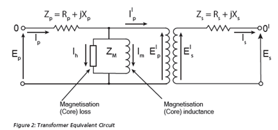
Accordingly, the magnetization losses are low (i.e., a small Ih in Figure 2) and the (shunt) magnetizing inductance is high, resulting in a very small magnetizing current, Im. The excitation current is the vector sum of these current contributions, Ih and Im. The inductive volt - amperes - reactive (VAR) requirements of the transformer are very low. Moreover, with non - saturated core magnetization, the transformer voltage and current waveforms contain very low harmonic content.
 During a GIC event, a quasi - dc current enters the ground-connected neutral of the transformer and splits equally between phase windings (on multiple phase winding transformers). If the zero-sequence reluctance of the transformer is low, the GIC biases the operating point on the magnetization curve to one side (see the top black dashed line in Figure 1). This bias causes the transformer to enter the saturation region in the half cycle in which the ac causes a flux in the same direction as the bias. This effect is known as half - cycle saturation. When the core saturates, it has reached the limit of its ability to carry a magnetic field; any field beyond the limit “leaks” out of the core and passes through the space around the core (air/oil) as “leakage flux”.
While the magnetic reluctance of the core is still low, the reluctance of the portion of the magnetic circuit outside the core is high. This results in a much - reduced value of shunt inductance and a large shunt current (Im) flows through the magnetizing branch. The inductive volt - amperes - reactive (VAR) requirements of the transformer can become very high (see the red excitation current pulse given a DC offset on the bottom vertical axis in Figure 1). With saturated core magnetization, the transformer voltage and current waveforms contain very high harmonic content.
Problems can occur with differential protective relays that are looking to see balanced primary and secondary currents. The transformer protection may trip as the primary current becomes disproportionately large (drawing increasingly more reactive current) compared to the secondary current.
Leakage flux is always present in a transformer that is carrying load. Because of the problems that it can otherwise cause, transformer manufacturers design and build their transformers such that the anticipated leakage flux is “managed” and has minimal impact on the long-term operation and life of the transformer. Leakage flux, however, is never anticipated from the excitation of the transformer. The high peak magnetizing current pulse (red in Figure 1) produces correspondingly higher magnitudes of leakage flux (as given by the red waveform on the left side of Figure 1) that is also rich in harmonics.
The influence of excessive leakage flux on the transformer is generally thermal. Leakage flux in transformers that links any conductive material (including transformer windings and structural parts) will cause induced currents that result in almost immediate localized, unexpected, and severe heating due to resistive losses. Paint burning off transformer tank walls might be considered an asset owner’s best-case example!
Transformer designs that include core bolts are a concern because, should the stray flux link such bolts located at the bottom of the windings and cause the surrounding oil to heat to 140C, this could result in bubble evolution that ultimately leads to transformer failure. For any given design, a finite element analysis will reveal the leakage flux paths and weaknesses, if any, in the design. If a transformer is lightly loaded, and therefore its operating leakage flux is light compared to its full load rated flux, the unit may be able to handle the additional leakage flux introduced by GIC.
In summary, a saturated transformer becomes a reactive energy sink, an unexpected inductive load on the system, and behaves more like a shunt reactor. Transformer differential protective relays may trip and take the transformer out of service. Excessive leakage flux can result in detrimental overheating, or in some designs, winding damage due to resulting high winding circulating currents. Separately, the magnetizing current pulse of a GIC inflicted transformer injects significant harmonics into the power system. The resultant impact of these changes in the transformer(s) constitutes the second order effects of GIC.
Second Order Effects of GIC
Many agree that the more concerning impacts of GIC are its indirect effects on the power system and its components. The effect of a transformer morphing into a shunt reactor on the power system is best understood after a review of shunt reactors and capacitors.
Shunt capacitor banks are used to offset inductive effects on the power system (to support voltage) while shunt reactors are used to offset the effects of capacitance on the system (to reduce voltage). Typically, shunt capacitors are switched in during periods of high load, and shunt reactors are switched in during periods of light load. The same effects can be achieved, within rating limits, by varying the excitation of generators, i.e., operating them as “synchronous condensers”. Static VAR compensators (SVCs), which combine capacitor banks and reactors, provide similar compensation and voltage support, with very fast automated controls. Many power systems once had dedicated synchronous condensers (rotating machines). However, capacitor banks are cheaper and as capacitor technology advanced to the point where reliability became excellent, synchronous condensers were retired.
Inductive reactance, which is expressed by XL = 2πfL, indicates that as inductance, L, goes down, inductive reactance drops. Saturated transformers have low shunt magnetising inductance so they draw high currents; they look like shunt reactors on the system, dragging down the system voltage.
Capacitive reactance is expressed by XC = 1/(2πfC). From this, it is easy to see that a capacitor presents as an open circuit (infinite impedance) to DC current; this underpins the effectiveness of series capacitor blocking in very long transmission lines as a GIC mitigation strategy. In contrast, as frequency goes up, capacitive reactance drops so capacitor banks have lower impedances to harmonics and draw larger currents when harmonics are present.
While saturated transformers draw large currents, forcing system voltage down and potentially overloading long transmission lines, capacitor banks also draw large currents due to the presence of harmonics, partially offsetting the inductive effects. Essentially, the saturated transformers are in a tug - of - war with the capacitors on the system. Modern shunt capacitors have very low loss and are therefore less susceptible to transient heating damage due to excess current. However, large currents may affect other components in capacitor bank installations, resulting in damage and unwanted tripping. Voltage imbalance and overvoltage protection may also be “fooled” by harmonic voltage spikes and cause unwanted trips. Finally, overcurrent protection may also operate spuriously in the face of harmonic currents. Similar issues may apply to SVCs. Harmonic filters for SVC banks create parallel resonances, which can exacerbate voltage disturbance issues and result in tripping of the protection devices.
Rotating machines have fairly high thermal inertia, so generators operated as synchronous condensers have a higher probability of staying on line. However, generators can also be affected by GIC currents. These effects include additional heating, damage to rotor components, increased mechanical vibrations and torsional stress due to oscillating rotor flux caused by increased negative sequence harmonic currents. The harmonic content of negative sequence currents can also cause relay alarming, erratic behaviour or generator tripping. If VAR resources are exhausted during a GMD event, specifically capacitive voltage support, voltage collapse can occur.
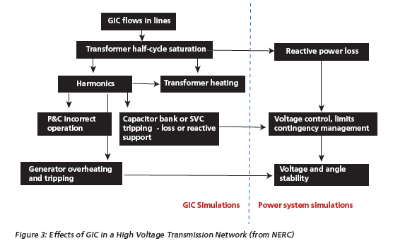
NERC’s 2012 Special Reliability Interim Report: Effects of Geomagnetic Disturbances on the Bulk Power System provides a block diagram that illustrates the effects of GIC, culminating in a threat to system voltage and angle stability (Figure 3).
Special Dispensation about the Effects of GIC on CTs and protective relays
It is important to have accurate measurements of system state during abnormal operating conditions. For these purposes, the industry has predominantly relied upon conventional instrument transformers – such as a current transformer (CT); a potential (or voltage) transformer, which may be inductive (PT/ VT) or capacitive (CCVT); or a combined current and voltage instrument transformer. An instrument transformer (IT) is “intended to reproduce in its secondary circuit, in a definite and known proportion, the current or voltage of its primary circuit with the phase relations and waveforms substantially preserved.” The electromagnetically induced current or voltage waveform(s) in the secondary circuit(s) of the IT should then be of an easily measurable value for the metering or protective devices that are connected as the load, or burden, on the IT.
In as much as a traditional, ferromagnetic IT has a magnetic core, ITs are influenced by GIC much like a power transformers. If an IT is pushed to a non - linear region of its saturation curve (i.e., its operating curve), due, for example, to a DC flux shift, the accuracy of the IT will significantly decline. While it is true that ITs typically operate at lower magnetization levels than power transformers because reading accuracy must be maintained in the face of large fault currents (i.e., they have more built - in margin on the curve), there is no way of knowing whether the magnitude of GIC in the system will saturate the core despite its margins, or if remanence was pre - existing in the core and already compromising the IT’s performance. In short, there will always be uncertainty about the reliability of system state measurements provided by ferromagnetic instrument transformers during a GIC event.
Moreover, when currents and voltages become rich in harmonics, even if the IT is not operating in a saturated state, the accuracy of the measurements will decline. Unfortunately, there is no on - line method of validating whether the instrument transformer is operating in a non - saturated state and, therefore, within its window of accuracy (i.e., the pseudo - linear region of its saturation curve at 50 or 60 Hz) or in a saturated state and, therefore, outside the realm in which it can accurately reproduce measurements.
It must also be remembered that protective relays operate based only on their inputs. If a CT, for example, is supplying a distorted waveform due to the effects of harmonic saturation, the relay may respond in a different, and unwanted, way than it does to nearly sinusoidal inputs.
FERC/NERC Regulation
Federal regulations designed to protect the electric grid in the USA from the potentially severe and widespread impact of a geomagnetic disturbance (GMD) are in the process of being adopted. Following several years of study, the Federal Energy Regulatory Commission (FERC) initiated a rulemaking in 2012, the first of its kind, directing NERC to develop and submit for approval Reliability Standards to protect the grid from the impact of GMDs.
In Order No. 779, FERC determined that the risk posed by GMD events, and the absence of Reliability Standards to address GMD events, posed a risk to system reliability that justified its precedent - setting order directive to NERC to develop Reliability Standards to address the issue. To expedite the standards - setting process, FERC ordered NERC to develop mandatory standards in two stages, both of which are now underway.
In the first stage, FERC directed NERC to submit Reliability Standards that required owners and operators of the bulk-power system to develop and implement operational procedures to mitigate the effects of GMDs to ensure grid reliability. These operational procedures were considered a “first step” to address the reliability gap and were approved by FERC in June 2014. These standards became mandatory on January 1, 2015.
In the second stage, FERC directed NERC to provide more comprehensive protection by requiring entities to perform vulnerability assessments against a “benchmark” GMD event and develop appropriate mitigation strategies to protect their facilities against GMD events. These strategies include blocking GICs from entering the grid, instituting specification requirements for new equipment, and isolating equipment that is not cost effective to retrofit.
The standard to implement the second phase of NERC’s GMD program is known as TPL-007-1. As of November 2015, FERC continues to deliberate over its approval. The initial Notice of Proposed Rulemaking (NOPR) comment period, which closed in May 2015, was extended until October 22, 2015 to allow for additional commenters to submit their views regarding the GMD benchmark. FERC ordered NERC to make changes to the proposed standard including: refining its definition of the benchmark event; requiring the installation of monitoring equipment wherever there are reliability gaps; and setting deadlines for completion of corrective actions. FERC is also considering shortening NERC’s proposed 5-year period for compliance.
Tags: current, electric, geomagnetically, GIC, induced, power, systems, transformer


