Discontinued
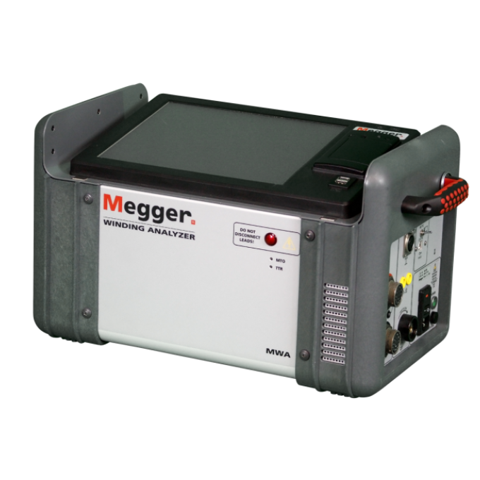
MWA300 and MWA330A three-phase ratio and winding resistance analysers
Compact and lightweight
55 % smaller and 40 % lighter than individual units for increased portability in the field
TTR and resistance testing combined
Save time and reduce the inconvenience of making separate connections for each test
Single PowerDB software platform
Save time with only one set-up and one easy-to-use test form
Built-in automatic core demagnetisation for safety
Avoid core saturation problems with a core demagnetisation function that safely demagnetises the transformer core after DC testing



About the product
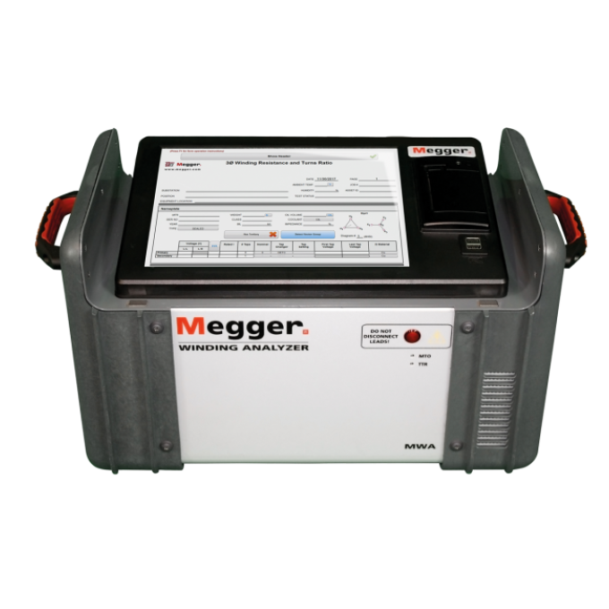
The Megger MWA300 and MWA330A three-phase ratio and winding resistance analysers are advanced transformer test systems that provide complete ratio, phase, and winding resistance measurements with only one three-phase lead set connection. What’s more, they offer portability, a reduced set-up time, and increased job safety.
Once connected, the MWA300 and MWA330A perform DC resistance measurements on all high- and low-side windings without reconnection. It has an eight-terminal/six-winding resistance measurement capability and doesn’t need any interconnected boxes, allowing you to test all phase windings without having to disconnect and reconnect leads.
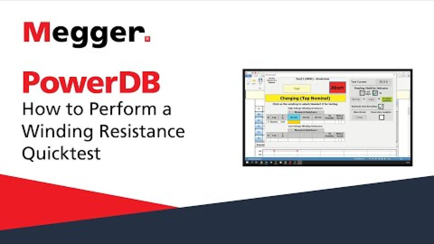
The MWA300 and MWA330A save you even more time by using a single software platform: PowerDB. This means you only need one setup and one easy-to-use test form.
The MWA300 and MWA330A can be used to effectively test power transformers, distribution transformers, CTs and VTs, and motors and generators. The following tests/functions are easily performed with a single instrument and one three-phase lead set connection:
- Three-phase turns ratio
- Three-phase winding resistance
- OLTC continuity (make-before-break)
- Three-phase core demagnetisation
- Magnetic balance/flux distribution
- Excitation current
- Polarity and phase angle deviation
- Auto vector detection
- Heat-run test
The MWA300 is externally controlled by PowerDB software running on an external PC. The MWA330A, on the other hand, comes equipped with its own built-in computer that can be operated via a 305 mm (12 in) colour touch screen display and can store up to 100 000 data sets.
Technical specifications
- Automation
- Yes
- Max output current (DC)
- 10 A
- Single-phase/3-phase capability
- 3-phase
Further reading and webinars
Related products
Troubleshooting
Verify that the INT PC/EXT PC switch located on the side panel of the MWA is set to EXT PC. Power down the MWA and your computer. With your PC connected to the MWA, power on your PC and the MWA.
Some antivirus software can also block communication to your PC. If possible, temporarily disable your antivirus. This is a quick method but not the preferred, or may not be allowed by your IT department. Within your PC antivirus there are ways to allow exemptions for certain programs and IP addresses. Check to see if “PowerDB.exe”, “MTOTestXP.exe”, and “MTOSetup.exe” are approved programs; if not, add them to the exempt list. Additionally, allow an IP Address range of 169.254.1.1 through 169.254.1.10 to be exempt.
If controlling the MWA with your PC, close Power DB and open it again, open your form and start testing. If it happens again, a full power down of the MWA and your PC is recommended. If the problem persists, then we recommend that you update your software to the latest version of Power DB.
If the onboard computer of the MWA freezes, power down the MWA and restart. If this problem persists, then you will need to update the software on the onboard computer. Download the “Transformer Test Instrument Software Update” for the MWA330A from the update section. Make sure to read the instrument update instructions prior to installing.
There are files within Power DB that are used to control the MWA; occasionally, these may be bypassed during installation. If you are not running the latest version of Power DB, then you can update Power DB and install this additional software as part of the update. When installing Power DB, make sure to select “MWA USB Drivers” under the Additional Software prompt. If you are updated to the latest version of Power DB, or do not wish to update, then you can install the specific software needed.
- Click “No” on the prompt
- Close Power DB
- Browse to the following folder on your PC: C:\Program Files (x86)\PowerDB Inc\PDB Optional Files\MTOSetup
- Double click on MTO_PDB_Update_Release_XXXX.exe (NOT MTO_PDB_INSTALL…)
- Click “Next” and proceed with the install
- After the install, click finish and resume testing
Verify that the INT PC/EXT PC switch is set to INT PC. Power off the MWA and then power it back up. If still not able to communicate then the unit will need to be returned to Megger or an authorised repair centre.
Note: You can also connect a PC that has Power DB installed and operate the unit with your PC if you need a quick fix in the field. Just make sure the switch is set to EXT PC and power the MWA off and then on with your PC connected.
Once testing begins, several errors can appear that result from improper connections, improper instrument configuration, instrument malfunction, or a faulty asset under test. If an error occurs, repeat the measurement before performing any corrective action to verify it is not a glitch.
Verify that the form's nameplate data matches the transformer's nameplate. Pay particular attention to the transformer's vector diagram, voltage, and power rating.
Check all connections to make sure the clamps are on the correct bushing terminals and verify proper connection to the MWA. Make sure there are no unwanted grounds or shorts connected to the terminals.
You can perform functional tests with the MWA to verify that the unit is operating correctly. In some cases, it may be easier to check connections and swap leads or connection points on the transformer; other times, it might be more convenient to perform quick functional tests. Follow steps one and two below to verify that the MWA is working correctly.
- Megger provides a test jig with the MWA to test its TTR functionality. Use a form set for a YNyn0 transformer and connect the test leads to the metal portion of the test jig next to the markings. Perform the test; the results should be a ratio of approximately 1:1 with a phase deviation of +/- 6 minutes and an excitation current of 0 to 0.5 mA. Note: The ratio will be between 0.9980 and 1.0020; this is due to the internal measuring circuits of the MWA and is expected since you are essentially connecting the leads together and not connecting to a transformer. Also note that this test is only for checking the instrument's general function; you should not use the test jig to calibrate your MWA.
- To test the winding resistance functionality of the MWA, you will need some conductive metal, e.g., a wrench or pipe. Something approximately eight inches or more in length will be helpful. Use a winding resistance form set to YNyn0 and connect the H1 clamp to one side of the object and the H0 clamp to the other. You should obtain a resistance value. Continue to measure the resistance using the other leads, i.e., between H2 and H0, then H3 and H0. If connected at the same spot, they should yield the same resistance value with a little deviation due to the connection points. Repeat the test with the low side leads, i.e., X(1,2,3) leads to X0.
If the functional tests do not pass, there is an issue with the MWA or the test leads. You must return the MWA to Megger or an authorised repair centre for evaluation. If the functional tests pass, the MWA is working. In this case, the error is either due to your connections or an issue with the transformer. Proceed as follows:
- Verify that the clamps have a solid connection. The clamps are Kelvin type, so you need to connect both sides of the clamp to the bushing terminals. Oxidation can build up on the terminals, so make sure they are clean such that the clamps can make a solid electrical connection. Connect to a different part of the terminal, if need be, to check for a better connection.
- Swap the leads with a different phase's leads to ensure that the error is not following the leads and remains on the phase you were initially testing.
If you have verified that you do not have a connection problem or setup mistake and have confirmed the MWA's integrity, then the error message may be due to a problem with the transformer. See the “Interpreting test results” section for interpretation and recommendations.
Note: If the excitation current is too high while performing TTR tests, you can lower the test voltage to 40 V or 8 V. If the error persists, you may have a short-circuited transformer winding, and further investigation is warranted.
This error means that the instrument cannot produce the required current. Verify that all leads are connected correctly to the MWA and the transformer under test. The clamps are Kelvin type, so both sides of the clamp need to connect to the asset. Next, verify the error on multiple phases. If connections are correct and sound, and the error occurs on multiple phases, it is most likely a problem with the MWA. You must return the instrument to Megger for repair.
Interpreting test results
The MWA is a combined transformer turns ratio (TTR) and winding resistance (WR) test set, so the data interpretation criteria differ for each test. Still, there are a few commonalities to the assessment approach you should adopt for each. First, the best evaluation method is comparing newly acquired measurements against previous test results to ensure nothing has changed. If no previous test results are available, then comparing the test results for each of the three phases to the others is also helpful. Finally, differences in measurements indicate winding problems, assuming that you have performed your tests like the previous ones, e.g., the same test settings and conditions (temperature). The MWA can detect winding problems that include short-circuited winding turns, open-circuited turns, or broken or corroded connections.
A TTR test is used to verify that the transformer vector diagram and ratio are correct per the nameplate. The measured ratio should be within 0.5 % of the nameplate ratio for all taps.
In addition to comparing against the nameplate, you should compare the measured ratio of one phase to the ratios measured for the other two phases. The industry standard (factory) permits a maximum difference of 0.5 % from the average of the three ‘phase winding’ ratios. Field readings may vary slightly more than this due to the many variables. If all ratios are within 1 % of each other, they are acceptable.
Changes in ratio values or deviations from nameplate are an indication of shorted turns or open windings, incorrect assembly or connections in tap changers, and high resistance connections.
Comparing absolute resistance values in the field with factory values may be difficult due to the problem of precisely estimating the winding temperature. A transformer OEM can control the winding temperature in a factory test setting, and direct access to the windings is often available. On the other hand, field testing requires winding resistance to be measured through the bushings, and the test is performed at the winding temperature available, which is not always precisely determined. For this reason, if comparing field measurements to factory values, measured values within 5 % are generally acceptable.
Since field measurements are generally made in different conditions than factory measurements, comparing each ‘phase winding’ resistance value to the others is better. IEEE allows a maximum resistance difference of 2 % between phases for liquid-filled transformers.
Changes in resistance values (after temperature compensation is taken into account) are indications of shorted turns, broken strands, faulty or corroded connections between winding and bushings, or within a tap changer.
If performing a winding resistance test on a transformer equipped with a load tap changer (LTC), it is advisable to continue injecting DC current into the respective winding while switching through the taps. By maintaining the current, you test the LTC’s ‘make before break’ functionality, verifying that it is operating correctly. If the current is interrupted during a tap transition, then this indicates that the LTC is not working correctly in that transition.
User guides and documents
Software and firmware updates
Transformer Test Instrument Software Updates for MWA330A and DELTA4310A
Update Instructions
Please read these instructions before performing the update, you can download them here.
DELTA and MWA Updater
latest version
The following components have been updated:
PowerDB ________________ V11.2.10
MTOTestXP ______________ 2019.12.03.1
Delta Manual Control ______________ 2.0.9.51.0
Instrument Config ______ 1.0.20023.1919
Splash Screen __________ 1.0.21075.830
Factory Config _________ 1.0.21122.850
Megger Update Manager __ 1.0.21165.1032
Recommendations
- Megger recommends that you return your instrument annually for calibration verification.
- Any instrument returned for re-calibration will be updated with the latest firmware and software versions.
- Certified Factory Calibration is valid for one year.
Attention
Incorrect installation of updates or incomplete updates may cause the equipment to become unusable.
If damage occurs from improper updates, the customer may be responsible for repair costs.
Software updates for MWA330A and DELTA4310A
Download this zip file, extract, and run the executable.
256bit Hash:
be0628b2014fffeca839036dae42c3d1a6c5c73d79a2e5f2fc6d0716667ef9d3
