New
IMT100 industrial multi-tester
Exceptionally safe to use
The fast-detecting circuitry reduces the likelihood of damage to the instrument if accidentally connected to live circuits or across phases. It is designed with live circuit detection and test inhibit all measurements with user notification
Complete suite of insulation resistance
It comes with a unique guard terminal for leakage current detection with a resolution of 0.1 μA. It can perform spot testing, timed testing, and Diagnostic Polarisation Index (PI) and Dielectric Absorption Ratio (DAR)
Ready for outdoor conditions
The IMT100 is manufactured in an over-moulded case increasing protection and robustness, and achieving an IP54 weatherproof rating. It comes supplied in a multi-purpose industrial carry case ideal for bringing additional accessories and field tools
Worry- free battery supply
It comes fitted with six NiMH rechargeable batteries and a mains battery charger kit that provides over 1200 insulation tests, or 1200 continuity tests. The IMT100 can also be used with six standard 1.5 V Alkaline (AA), 1.5 V Lithium (LiFeS2), or 1.2 V NiMH batteries
Full set of detachable test leads
The supplied test leads come with interchangeable clips and probes for different applications. The set includes photovoltaic connectors, a remote probe, and insulation resistance lead set, low resistance Kelvin clips and probes, and a temperature probe


About the product
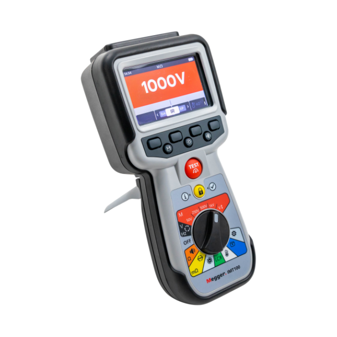
The IMT100 industrial multi-tester is a versatile instrument with a complete suite of insulation and low resistance testing capabilities, plus continuity, inductance, capacitance, voltage, and temperature measurements.
Additionally, the instrument can test insulation resistance from 100 Ω up to 200 GΩ, with test voltages of 50 V, 250 V, 500 V, 1 kV, and selectable variable voltage. The instrument includes a guard terminal, and supports several diagnostic insulation resistance functions including spot reading, polarisation index ratio, and timed insulation testing.
The IMT100 comes with a unique four-wire digital low resistance function that includes a stable power supply that can deliver 200 mA in long circuits with a resistance range from 1 mΩ up to 10 Ω. This unit offers different test modes selectable through a soft keypad, including bidirectional, unidirectional, automatic, and continuous. The rotary switch and soft keypads are easy to operate, with or without gloved hands, and the instrument’s full colour graphic display makes it easy to select functions and take readings.
The unit also has a supplied thermocouple (CAT III to 600 V) that enables you to test temperature and insulation resistance compensation.
What’s more, the LRC function allows the IMT100 to automatically determine if the main element of the load is inductive, capacitive, or resistive, and displays the result on screen. It also gives you the ability to select each function and frequency to 120 Hz or 1000 Hz.
The IMT100 comes with data storage management for up to 256 test results with individual tag names and dates. These can be downloaded to a USB drive and are also accessible within the instrument via a dedicated colour-guided recalling test results dashboard.
This instrument is designed to be exceptionally safe to use. The fast-detecting circuitry reduces the likelihood of damage to the instrument if accidentally connected to live circuits or across phases.
Occasional software updates may be issued on the Megger website, and the instrument can be updated by simply connecting a USB drive to the IMT100 with the firmware update file in the root directory. The IMT100 will start the update process automatically.
FAQ / Frequently Asked Questions
The IMT100 is one of the more unique instruments in the market. Coming with a full colour graphic display, it features 13 testing functions, capable of testing resistance, continuity, and insulation resistance in systems,, combining the two, three and four- terminal methods,, meeting (and exceeding) the testing ranges and accuracy levels required by the industry. Additionally, it meets the IEC 62446 for PV testing and additional tests, the UN Regulation UN EEC R100 for Electric Vehicle testing, and the safety protection conditions required by the IEC61010 and EMC IEC61326. The instrument comes in a multi-purpose industrial carrying case with a full set of test leads, rechargeable batteries with a battery charger, and storage for up to 256 tests that can be downloaded to a USB drive.
Yes. The IMT100 can be used in photovoltaic installations to performs tests under the IEC62446 for PV testing and additional tests. It is ideal for installations with voltage systems equal and under 1000 V AC and DC. It solves a range of testing needs from domestic,, to industrial and utility scale installations.
The IMT100 can be used to perform tests under the IEC62446 for PV testing and additional tests. In the DC side, it can test voltages up to 1000 V, check the polarity of the voltage, test the capacitance of the installation, measure the temperature of the different components, and test the diodes of the junction boxes in the photovoltaic panels. Additionally, the instrument performs a comprehensive diagnostic range of insulation tests., and can perform low resistance tests to confirm the continuity and correct equipotential bonding of the installation. In the AC side it can be used to test voltages up to 1000 V, test the capacitance, inductance, and resistance of different components of the installation, and can check the correct phase rotation of the installation. Finally the versatility of the instrument allows technicians and repair centres to use it as a fault-finding tool for a wide range of AC and DC loads
Insulation resistance tests can be carried out at the following settings: 50 V, 250 V, 500 V, 1 kV, and it offers user- selectable variable voltage. The IMT100 is fitted with a guard terminal that conducts leakage currents away from the measured circuit to reduce errors.
IR: Insulation resistance. PI: Polarisation index at 1 minute to 10 minutes ratio. DAR: Dielectric absorption ratio at 15 or 30 seconds, to 60 second ratio. T(s): Time IR is selectable from 1 minute to 10 minutes, in 1-minute increments. 3P: Three-phase, to test insulation resistance phase- to- phase.
Yes. This makes the IMT100 a unique instrument in the market as it meets the UN EEC R100 Regulation for Electric Vehicle testing. It also allows manufacturers, workshops, and service centres to test crucial components safely and reliably in electric vehicles (HEV, PHEV, BEV). It does this, using four-wire low resistance, two wire continuity bonding, and three- wire insulation resistance, in addition to testing voltages, temperatures, and recording test results
Yes. The IMT100 can be used for testing and fault-finding on assets during installation, commissioning, start-up, and regular maintenance at domestic and industrial levels, as well as in production lines.It is ideal to use in CAT III 600 V environments up to 3000 m, and system voltages up to 1000 V AC and DC
Yes. Rotating machinery is one of the most common loads found not only in photovoltaic installations, but also in production lines in the industry. The IMT100 offers the most common initial static analytic tests, like motor direction of rotation, continuity, low resistance, three phase insulation testing, temperature testing, and compensation.
Further reading and webinars
Related products
Troubleshooting
Any warning conditions while using the IMT100 will appear on the display with an error code. Screen instructions will guide you through the troubleshooting process.
If the instrument does not behave as normal, and the warning messages do not disappear, this could be an indication that the instrument has a fault it needs to be repaired.
In depth details can be found in the instrument’s user guide, or via our technical support lines, however the below outlines the warning messages and their meanings:
- Test failure - Lost connection
Should the connection be lost during the test, the IMT100 will notify you. You can re-make the connection then restart the test after a few seconds by pressing the test button or by reconnecting to a test piece. Failed export
If the export fails, the IMT100 will notify you. This may be because the receiving USB device is faulty, is disconnected, full, or in some other way fails.The IMT100 will return to its previous screen.
Fuse Failure
If a fuse fails, no measurements can be carried out. A message will appear each time you try to run a test.Close the message by pressing tick/check button and refer to the user guide
NOTE: A fuse failure warning could indicate a very low insulation resistance. Check the lead connection, and try again.
- Battery Low
The battery is too low to perform a test. Please charge the batteries or replace them to continue using safely the instrument. Charging Fault
A generic charging fault warning screen.Turn the instrument off and disconnect the charger. Then reconnect and try again.
Battery not chargeable
The battery settings are not correct to allow battery charging.Check the correct battery type is in the instrument. Refer to the user guide for more information.
Check the battery settings are NiHM. Refer to the user guide for more information.
Battery Charging Warning
Only NiHM battery cells are rechargeable.
Do not attempt to recharge alkaline or lithium cells, this action is a high potential fire hazard.When charging the IMT100 while the instrument is off, an animated battery will display across the screen to show charging is taking place. Once the battery is fully charged the screen will display a solid green battery.
- Code 1000 or higher
Follow the instructions on the screen. The instructions will suggest rebooting the instrument and if the problem persists, contact Megger. The screen displays a “Voltage Detected” warning during a test.
Even if you don’t expect it, a voltage can be present or can develop during a test. The instrument will inhibit a test when the voltage detected exceeds dangerous limits and will stop the test. This voltage threshold can be set as a lockout voltage.The lockout voltage is active on all test modes. It is hard-coded to activate at 20 V. The only exception is the insulation resistance tests, where the lockout voltage can be set as 20 V, 30 V, 50 V, or 75 V.
If the instrument does not behave as normal, and the warning messages do not disappear following the screen instructions, please contact our technical support lines or an authorised Megger service centre for evaluation and repair.
Interpreting test results
A low resistance measurement is typically a measurement below 1 Ohm. At this level, it is important to use test instruments that will minimise errors introduced by the test lead resistance and contact resistance between the probe and the material under test.
At this level, standing voltages across the item being measured, like thermal electromotive forces, known as EMF, at junctions between different metals can cause errors that, need to be identified.
A summary of the different methods used to measure resistance is shown below for a better understanding of the instrument capabilities and testing ranges.

Testing conditions at the time of tests can also provide essential information. Maintain records of the temperature, humidity, altitude, and any electrical interference recorded by the instrument to allow space for further corrections in the tests results.
There are different approaches towards expected values on a test. International standards suggest best practices and expected values. Notably, for photovoltaic applications, the UL 2703 suggests specific applications for racking assemblies, clamps and module fasteners, and grounding lugs, while the IEC 60512 suggests specific values on connector resistance, which is applicable for many uses, including photovoltaic and electric vehicles.
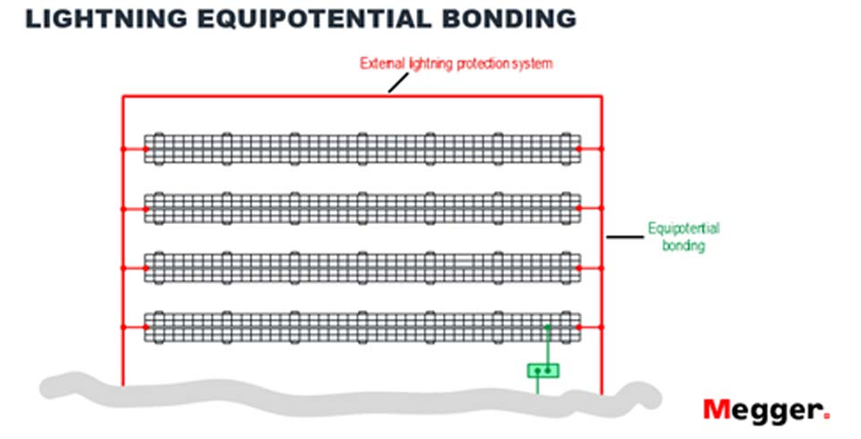
This test is vital when detecting changes in electrical bonding and mechanical equipotential structures, particularly in photovoltaic systems exposed to heavy winds, storms, snow, and corrosive environments. Below, there are some examples of where to look for these changes in equipotential bonding points:


A good insulation resistance value means a relatively high resistance to current flow, as well as the ability to maintain a high resistance.
Insulation resistance is highly temperature dependent, and thus the results should be corrected to a standard temperature, usually 40ºC. While temperature effects will be covered later, a good rule of thumb is that for every 10 º C increase in temperature, the current doubles, and resistance halves. The key to making the test valuable is consistent timekeeping, effective record keeping, and constant trending of results.
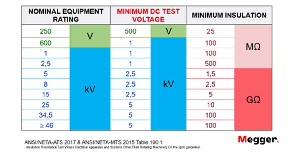
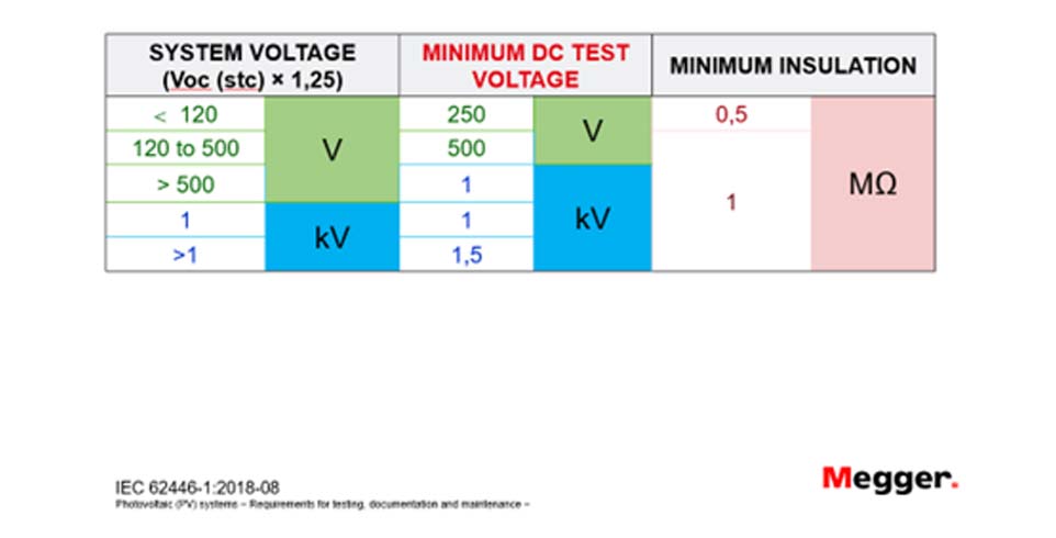
Minimum acceptance values for insulation testing and test voltages are recommended by international standards, like the IEE and the ANSI, based on the voltage rating of the system to be tested. Some guidance is provided in the following tables:


The resistance and insulation resistance tests of a component can vary with its temperature. To use the instrument with the temperature compensation function enabled, a temperature measurement must be carried out to establish the temperature of the unit under test.
The thermocouple supplied with the IMT100 is set as default as type “T” and can also be configured for “J” and “K” type thermocouples.
The temperature compensation is set to “OFF” by default, and it is available in a selection of test range sub-modes:
- Insulation resistance
- IR tests
- Three phase test
- Timed test
- DLRO - Low Resistance Ohmmeter
- Uni-directional
- Bi-directional
- Three-phase
Diagnostic insulation tests electrically stimulate the insulation and measure the response. Dependent upon that response, we can draw some conclusions about the condition of the insulation.
Diagnostic insulation testing covers a very wide range of techniques, and these are:
- Spot reading test(IR)
The spot reading test is the simplest of all insulation tests and the one most associated with lower voltage insulation testers; the test voltage is applied for a short, specific period of time. Polariszation iIndex tTest (PI)
This requires only two readings followed by a simple division.IEEE standard 43-2000, Recommended Practice for Testing Insulation Resistance for Rotating Machines, defines PI as the ratio of insulation resistance at 10 minutes divided by insulation resistance at 1 minute since the thermal mass of the equipment being tested is usually so great that the overall cooling which takes place during the 10 minutes of the test is negligible.
In general, a low ratio indicates little change, hence poor insulation, while a high ratio indicates the opposite.


PI results > 1.5 are regarded as acceptable by IEC60085:-01:1984 for thermal class rating A, and PI results > 2.0 for thermal class ratings B, F, and H.
Dielectric Absorption Ratio(DAR)
Measures resistance over time expressed as a ratio of resistance at time t2 divided by resistance at time t1.
The assumption is that insulation temperature does not vary widely over the duration of the test so the resulting DAR and/or PI value are temperature independent.
This test is defined as the ratio of insulation resistance at 1 minute divided by insulation resistance at 30 seconds.
In general, a low ratio indicates little change, hence poor insulation, while a high ratio indicates the opposite.
Timed insulation resistance test T(s)
A timed test will automatically terminate an insulation test after a preset time. The default timer is set to 1 minute and is adjustable within the settings function. This is a useful feature that saves you from watching the display for the full duration of the test, and the possibility of missing the 1-minute reading.
User guides and documents
FAQ / Frequently Asked Questions
Before testing, the measurement board will carry out a short a pre-test voltage check. If the lockout voltage is exceeded, you will see an overlay menu showing the current voltage measured. The overlay will disappear if the voltage is lowered below the lockout voltage threshold. The screen will immediately display a voltage detected warning message with the value of the present voltage. The lockout voltage is active on all test modes. It is hard-coded to Activate at 20 V. The only exception is the insulation resistance tests, where the lockout voltage can be set in the settings (as 20 V, 30 V, 50 V, or 75 V). Follow the test settings suggested in the user guide.
Temperature compensation is set to “OFF” by default.Temperature compensation is available in a selection of test range sub-modes:
- Insulation resistance
- IR tests
- Three phase test
- Timed test
- DLRO Low Resistance Ohmmeter
- Uni-directional
- Bi-directional
- Three phase
Follow the test settings suggested in the user guide.
Insulation resistance tests can be carried out at the following settings 50 V, 250 V, 500 V, 1 kV and the unit offers user- selectable variable voltage.The IMT100 is fitted with a guard terminal. The guard terminal is used to conduct leakage currents away from the measured circuit to reduce errors..Follow the test settings suggested in the user guide.
You can perform the following:
- IR: Insulation resistance.
- PI: Polarisation index at 1 minute to 10 minutes ratio
- DAR: Dielectric Absorption Ratio at 15 or 30 seconds to 60 second ratio.
- T(s): Time IR is selectable from 1 minute to 10 minutes, in 1-minute increments.
- 3P: Three phase, to test insulation resistance phase to phase
Follow the test settings suggested in the user guide.
A continuity test can be performed with test currents of 20 mA or 200 mA in the following options:
- Uni-directional
- Three phase continuity
- Bi-directional
Follow the test settings suggested in the user guide
A low resistance - DLRO (mΩ) test can be performed with a test current of 200 mA in the following options:
- Manual single direction test
- Auto single direction test
- Manual bi-directional test
- Auto bi-directional test
- DLRO three phase
Follow the test settings suggested in the user guide.
The IMT100 can be used in photovoltaic installations to performs tests under the IEC62446 for PV testing and additional tests. It is ideal for installations with voltage systems equal and under 1000 V AC and DC. It solves testing needs from domestic, to industrial, and utility scale installations.
The IMT100 can be used to perform tests under the IEC62446 for PV testing and additional tests. On the DC side, it can test voltages up to 1000 V, check the polarity of the voltage, test the capacitance of the installation, measure the temperature of the different components, and test the diodes of the junction boxes in the photovoltaic panels. It also performs a comprehensive diagnostic range of insulation tests. Additionally, it can perform low resistance tests to confirm the continuity and correct equipotential bonding of the installation. On the AC side, it can be used to test voltages up to 1000 V and test the capacitance, inductance, and resistance of different components of the installation. It can also check the correct phase rotation of the installation. The versatility of the instrument allows technicians and repair centres to use it as a fault-finding tool for a wide range of AC and DC loads as well.
The IMT100 is a unique instrument in the market that meets the UN EEC R100 Regulation for Electric Vehicle testing. It allows manufacturers, workshops, and service centres to test crucial components safely and reliably in electric vehicles (HEV, PHEV, BEV), using the four-wire low resistance, two- wire continuity bonding, and three wire insulation resistance apart from testing voltages, temperatures, and record test results.
The IMT100 can be used for testing and fault-finding assets during installation, commissioning, start-up, and regular maintenance at domestic and industrial levels, as well as in production lines.It is ideal to use in CAT III 600 V environments up to 3000 m, and system voltages up to 1000 V AC and DC
Rotating machinery is one of the most common loads found not only in photovoltaic installations but also in production lines in the industry.The IMT100 offers the most common initial static analytic tests, like motor direction of rotation, continuity, low resistance, three phase insulation testing, temperature testing, and compensation.


