ICMcompact stand-alone partial discharge detector
PD testing according to international standards
Perform factory acceptance tests that fully comply to the IEC 60270 standard
Available for indoor or outdoor installations
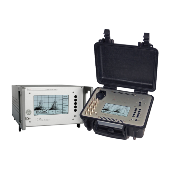
Its three housing versions adapt the instrument to the intended indoor or outdoor application environment.
High modularity
Configure your ICMcompact with a wide range of optional features and accessories to fulfil your specific needs


About the product
The ICMcompact is Power Diagnostix’s stand-alone partial discharge detector. This digital instrument has been designed for the condition evaluation of medium and high voltage (MV and HV) insulation and is typically used for quality assurance and quality control, including factory acceptance tests (FAT), end-of-line testing, and post repair. It is also suitable for field use.
The ICMcompact is primarily intended for the following assets:
- Factory acceptance tests for MV and HV assets
- Distribution transformers
- Instrument transformers (voltage transformers and current transformers)
- MV and HV cables
- Electronic components (eg., insulated-gate bipolar transistors)
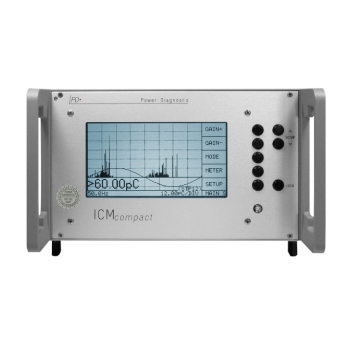
The ICMcompact has a simple push-button interface and on-screen menus located in an embedded LCD panel. The display modes include a simple PD charge meter with adjustable ‘needle’ sensitivity, monochrome phase-resolved PD patterns for classification of defects, and a scope-like display showing phase-summed charge pulses superimposed with the applied voltage wave.
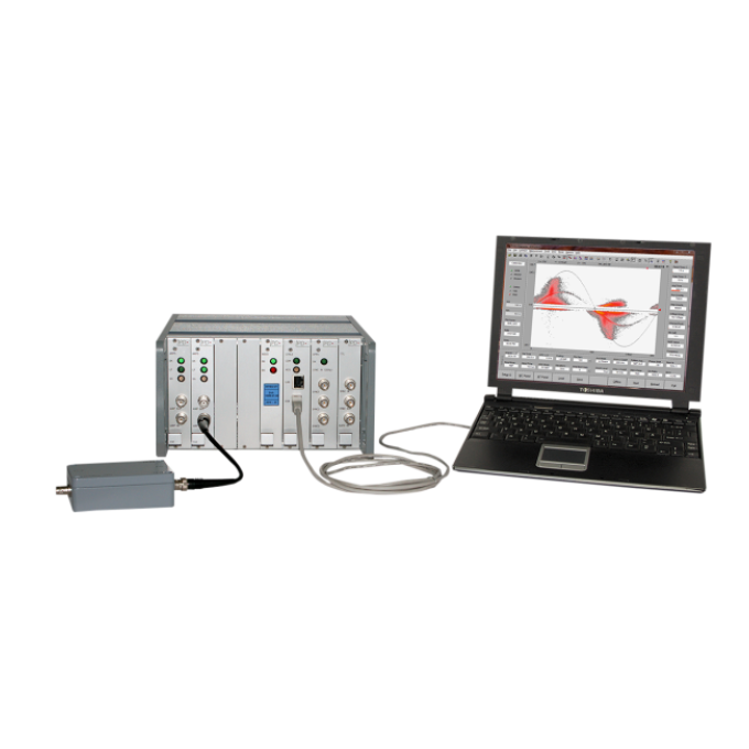
The ICMcompact is an autonomous unit, but it can be connected to a computer with installed Power Diagnostix software to capture screenshots or to implement remote control of the unit.
To adapt the ICMcompact to your specific needs, it can be equipped with numerous extras and additional functions:
- Partial discharge spectrum analysis
- Partial discharge fault location for cables with digital storage oscilloscope (DSO) function
- Radio influence voltage (RIV) measurement
- High voltage measurement (HVM)
- Analogue gating
- Four- or twelve-channel multiplexer
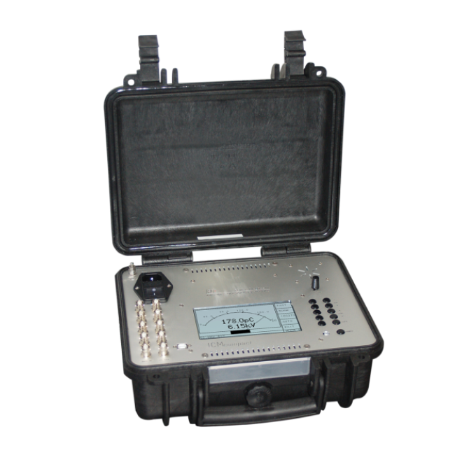
- Battery-operated and cordless device with up to three hours operation time (Explorer case only)
- LAN and fibre optic serial link
- Auxiliary inputs for recording additional data such as power and temperature
- Computer-controlled software
- Rugged case ICMoutlander for outdoor use
FAQ / Frequently Asked Questions
The IEC 60270 standard covers the measurement of partial discharges occurring in electrical equipment, components, or insulation systems when tested with AC voltages up to 400 Hz or with DC voltage. It specifies requirements for the measurement equipment and for calibrators that should be used for measuring. Additionally, it defines three possible measurement setups to ensure reproducible and comparable PD measurement results.Power Diagnostix’s ICMcompact meets all the requirements of the standard and thus guarantees highly accurate and reliable measurement results.
Observing the frequency spectrum of a harshly disturbed partial discharge signal allows to select frequency bands with fewer disturbances. Using such a selected frequency for a partial discharge acquisition, gives a largely improved signal-to-noise ratio resulting in a clear pattern acquisition. The combination of spectrum analyser and PD detector within one instrument opens a broad field of new possibilities when analysing isolation defects even with large noise.
An optional built-in multiplexer allows you to switch between several measuring channels for different test objects without the need to rearrange the test setup for each new test object. Power Diagnostix offers four- or twelve-channel multiplexers to speed up partial discharge routine tests by avoiding time-consuming setup modifications foür every test object.
Further reading and webinars
Troubleshooting
The power fuse might be blown. Unplug the unit and check the power supply fuse. This fuse is located on the rear panel of the ICMcompact (desktop and rack mountable version) or in the upper left corner (Explorer case version) above the on/off switch.
Another reason might be an empty battery, specifically in the case of battery-operated Explorer case models. Please check the battery level and recharge it if necessary.
A communications error might have occurred with the serial connection to the ICMcompact. Within the ICMcompact PC software, ensure that the serial COM port selected in the menu. “Options” > “Interface settings” is the COM port to which the ICMcompact is connected. Within the Windows Device Manager, check if the USB driver was properly installed. Then try rebooting both the ICMcompact and the PC.
On PCs running Windows 10 with the Creator’s Update (2017) the ICMcompact application window may appear very small on high resolution monitors. To enlarge the display size of the software, please take the following steps:
- Right-click on the application short cut on the desktop.
- Choose “Properties” from the context menu. This will open the “Properties” window.
- On the “Compatibility” tab, enable “Override high DPI scaling behaviour” and set “Scaling performed by” to “System”.
- If you have administrator rights, you can change the settings for all users by clicking the corresponding button.
- Approve the change with the button “OK”.
The RPA might be installed improperly (backwards). Make sure that the BNC connector marked with an incoming arrow leads from the sensor (quadrupole, CT, or coupling capacitor), and that the BNC connector marked by the outgoing arrow, leads to the BNC connector labelled “AMP IN” on the rear panel of the ICMcompact.
The pre-amplifier must be enabled if an RPA is connected. Ensure that “>RPA ON” is marked in the instrument menu. Try substituting the BNC cables to be sure that the problem is not in the cables themselves.
- First, check that the calibrator is still on. The calibrator will shut off automatically after several minutes without having its buttons pushed. Check that the low battery indicator is not showing on the LCD panel of the calibrator.
- The calibration pulse setting might be too weak for test setup. Try increasing the magnitude of the calibration impulse applied to the test setup.
- The calibration pulse on-screen might be present but too small to be easily visible. Try putting the ICMcompact into “SCOPE/Norm” mode. This will make the calibration pulse appear as a vertical bar, which makes it easier to see on the screen as it appears in the “Hold” mode.
- Sometimes the calibration pulse is lost if the high voltage power supply is connected to the test setup when the calibration is performed, even if the high voltage supply is completely powered off. Try physically disconnecting the high voltage supply from the test object during the calibration process. The calibrator is then only connected via the quadrupole of the test object and the coupling capacitor (if present).
If the problem persists, please contact our technical support department.
If you use the standard instrument version, please make sure that “ESYNC” in the “SETUP3” menu is active. If you use an instrument with the optional HVM functionality, please make sure that “SYNC” in the “SETUP3” menu is active.
Interpreting test results
The evaluation of a PRPD pattern enables you to determine the kind of fault within the test object. Most partial discharge (PD) faults, e.g., isolation damages, voids, surface discharges, or floating points, will have a completely different PD pattern.
- The typical criteria used to classify these patterns are:
- Phase position of the maximum PD
- Phase position of the starting electron
- The gradient of discharges
- The shape of discharges in the positive and negative half-cycle
- The absolute value of discharge in pC or nC
- Short-time or continuous discharges
For successful interpretation, it is also necessary to get as much information as possible about the test object and its environment. Such information can be, for example, temperature, installation condition, age of the test object, previous faults, or weather conditions. It is useful to store typical PD patterns of known faults in an archive, which can be done by using Power Diagnostix’s ICMcompact software. This customer-specific database will be helpful for later evaluation on other test objects.
User guides and documents
FAQ / Frequently Asked Questions
Besides the non-intrusive standard partial discharge (PD) test performed by measuring the apparent charge of PD pulses and derived or related quantities, an optional built-in Digital Storage Oscilloscope (DSO) acquisition board enables the ICMcompact to perform Time Domain Reflectometry (TDR) measurements for cable fault localization with a location precision of 1 m + 0.1 % of the cable length.
Depending on the level, nature, and source of the disturbing signals, the ICMcompact offers different options for noise handling. A noise level that is stable over the whole phase can be removed from the pattern by the low level discriminator (LLD) function. Disturbances that always occur at the same phase position can be masked with the window function. If the disturbance source is known, such as switching off a relay or a thyristor firing, the ICMcompact can be supplied with a TTL signal to blind out the PD measurement path. For the time the TTL input is (logically) high, no PD signal is recorded. In case the ICMcompact is used for PD measurements in an environment with high frequency (HF) disturbance, such as radar signals, corona discharge, or thyristor firing, it can be equipped with an optional gating function. The ICMcompact is connected to an external noise sensor, that picks up the disturbance signal. This signal is used as an effective noise reducer by blending out such impulse noise.
Often, the high voltage applied to the test setup is not in phase with the line voltage and may not even be the same frequency as the line voltage. In such cases, it is best to synchronize the ICMcompact with an external signal. Nevertheless, in the absence of an external synchronization signal, the ICMcompact will automatically synchronize with the sine wave of the line voltage of the ICMcompact’s supplying power. Therefore, an external synchronization signal is not mandatory but recommended.
The ICMcompact does not need any calibration, nor does it require any maintenance on a regular basis, as the PD measurement is a relative measurement that is calibrated with a reference source prior to a measurement being taken. The calibration impulse generator as the reference source, however, should be calibrated on an annual basis to ensure that its output signal remains within the recommended boundaries.
Power Diagnostix offers a broad range of PD sensors, cables, and other accessories to cover most of the possible testing situations with the ICMcompact. Please refer to Power Diagnostix’s accessories catalogue for further information.


