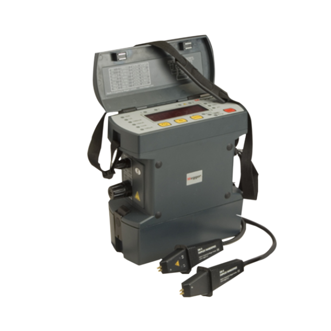
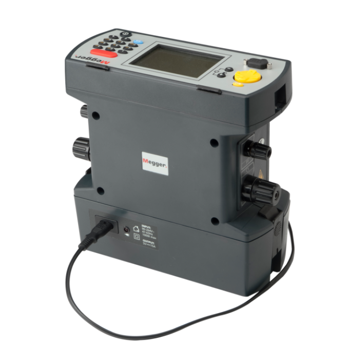
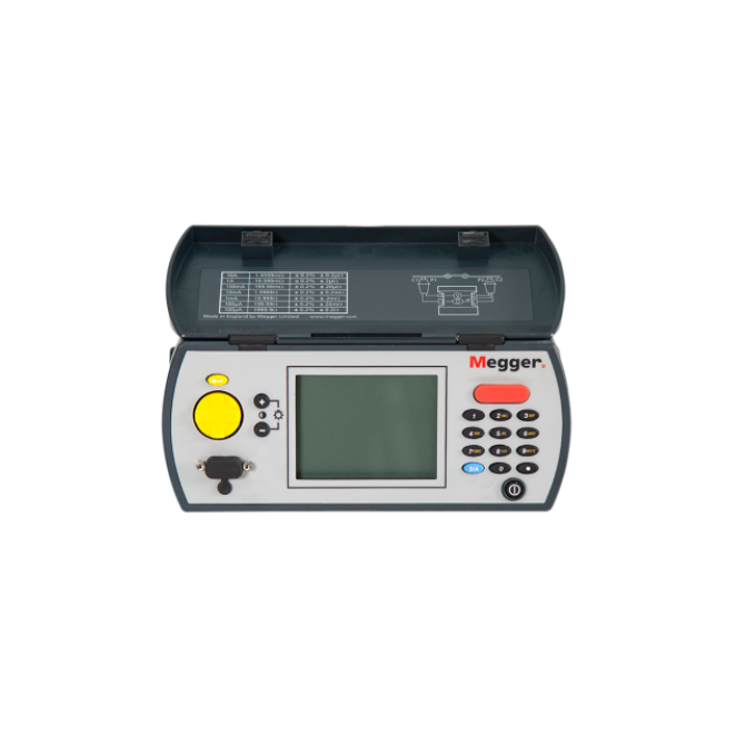
DLRO10 and DLRO10X digital low resistance micro-ohmmeters
Small, lightweight, and portable
Can be used in tight places and reduces the need for extra long leads and two-person operation
Automatically applies forward and reverse currents
Negates the effect of any standing voltages across the sample under test
Detects continuity in potential and current connections
Prevent erroneously high readings due to high resistance contact


About the product
The DLRO10 and DLRO10X digital low resistance micro-ohmmeters bring new standards to low resistance measurement (also known as the Megger ‘Ducter™’ test). Both are fully automatic instruments, selecting the most suitable test current, up to 10 A DC, to measure resistance from 0.1 µΩ to 2000 Ω on one of seven ranges.
If you desire more control over the measurement process, the DLRO10X uses a menu system controlled by a two-axis paddle to allow you to manually select the test current. The DLRO10X also lets you download results in real time and provides on-board storage for later downloads to a PC.
The DLRO10 uses a large, bright 4.5-digit LED display, while the DLRO10X has a large, backlit LCD. Both are visible under all lighting conditions and help reduce errors in reading results.
Both instruments are built into a strong, lightweight case that is equally at home in the field or the laboratory. They are light enough to be worn around the neck, enabling you to take them into areas that were previously too small to access.
Technical specifications
- Data storage and communication
- None
- Max output current (DC)
- 10 A
- Power source
- Battery
- Power source
- Optional mains adapter
- Safety features
- CATIII 600 V
- Safety features
- LED indicators
FAQ / Frequently Asked Questions
Low resistance ohmmeters have an application in a wide range of industries. They can help identify various problems that could lead to apparatus failure. In general manufacturing industries, motor windings, circuit breakers, busbar connections, coils, ground bonds, switches, weld joints, lightning conductors, small transformers, and resistive components all require testing for low resistance.
The following are some of the more typical applications:
- Motor armature - motor bar-to-bar tests
- Automotive assembly - cable leads in welding robots
- Power generation and distribution - high current joints, connections, and busbars
- Transformers - primary and secondary taps
- UPS - battery straps
- Wind turbine - the weather mast, roof cooler, control panels, nacelle-tower junction, nacelle-hub junction, and machine support
Assuming its correct installation, factors such as temperature, cycling, fatigue, vibration, and corrosion all work to cause the gradual degradation and increase in resistance of an electrical device. These influences build up over some time until a level is reached at which the device no longer operates correctly. The application will determine the critical degrading factor.
Environmental and chemical attacks are relentless. Even air will oxidise organic materials, while the ingress of moisture, oil, and salt will degrade connections even more rapidly. Chemical corrosion can attack the cross-sectional area of an element, reducing its effective size while increasing the component’s resistance. Electrical stresses, particularly sustained overvoltages or impulses, can cause welds to loosen. Mechanical stress from vibration during operation can also degrade connections, causing resistance to increase. These conditions result in excessive heating at the location where the component is carrying the rated current, based on the formula W=I²R. For example:
- 6000 A across a 1 μΩ bus = 36 Watts
- 6000 A across a 100 mΩ bus = 3600 kW
If left unattended, these problems can lead to failure in the electrical system containing the affected components. Excessive heating will ultimately cause failure due to burnout, which can open an energised circuit. Backup battery power supplies provide a good practical example of how degradation can occur under normal operating conditions. Changes in current flow cause the terminal connections to expand and contract, causing them to loosen or corrode. Additionally, connections are exposed to acid vapours, causing further degradation. These conditions cause a decrease in the surface-to-surface contact area with an associated increase in surface-to-surface contact resistance, ultimately resulting in excessive heating at the junction.
Industries that consume vast amounts of electrical power must include low resistance ohmmeter measurements in their maintenance operations. Not only does abnormally high resistance cause unwanted heating, possibly leading to danger, but it also causes energy losses, which increase operating costs. In effect, you are paying for energy you cannot use.
In addition, some industries have critical specifications on bond connections to ensure solid connections to ‘ground beds.’ Poor connections reduce the effectiveness of the ground bed and can cause significant ‘power quality’ related problems and/or catastrophic failure in the event of a major electrical surge. Several sub-assembly operations provide components to aircraft manufacturers that specify low resistance connections to the airframe. Strap connections between cells on a power backup battery system also require very low resistance.
A general list of industries includes:
- Power generation and distribution companies
- Chemical plants
- Refineries
- Mines
- Railroads
- Wind turbines
- Telecommunications companies
- Automotive manufacturers
- Aircraft manufacturers
- Anyone with UPS battery backup systems
Resistance (R) is the property of a circuit or element that determines, for a given current, the rate at which electrical energy is converted to heat per the formula W=I²R. The unit of measure is the ohm. The low resistance measurement will show you whether degradation has or is occurring within an electrical device.
Changes in the value of a low resistance element are one of the best and quickest indications of degradation between two contact points. Alternatively, you can compare readings to ‘like’ test specimens. These elements include rail bonds, ground bonds, circuit breaker contacts, switches, transformer windings, battery strap connections, motor windings, squirrel cage bars, busbar with cable joints, and bond connections to ground beds.
The measurement will alert you to changes that have taken place from the initial and/or subsequent measurements. These changes can occur from many influences, including temperature, chemical corrosion, vibration, torque loss between mating surfaces, fatigue, and incorrect handling. These measurements are required on a regular cycle to chart any changes. Seasonal changes may be evident when you review summer and winter data.
A low resistance measurement is typically a measurement below 1 ohm. At this level, it is essential to use test instruments that will minimise errors introduced by the test lead resistance and the contact resistance between the probe and the material under test. Also, at this level, standing voltages across the item being measured (e.g., thermal electromotive forces (EMFs) at junctions between different metals) can cause errors that need to be identified. A four-terminal measurement method should be employed with a reversible test current and a suitable Kelvin Bridge metre to eliminate or compensate for these measurement error sources.
Low resistance ohmmeters are designed specifically for these applications. In addition, the upper span on a number of these metres will range into kilohms, which covers the lower ranges of a Wheatstone bridge. The lower range on many low resistance ohmmeters will resolve 0.1 microhm. This level of measurement is required to do several low-range resistance tests.
Further reading and webinars
Related products
Troubleshooting
Make sure both C1 and C2 leads are making proper contact with your test specimen. Additionally, you can check for the continuity of those two leads using a multimeter to rule out any potential damage. If these two suggestions fail, it is likely because the current terminals C1 and C2 have become disconnected from the power board, in which case, you will need to send in the instrument for repair.
This is usually the result of the power battery losing charge due to normal ageing or terminal wires loosening. You can replace the battery on-site following the instructions in the User Guide. If that does not fix the issue, wiring issues may necessitate returning to Megger’s repair department.
Non-volatile memory batteries lose charge over time due to natural ageing. Replacing the battery is insufficient, as all calibration settings will have been lost. As such, you need to return the DLRO10 to Megger for recalibration.
The calibration constants have been lost. The DLRO will continue to work, but we can no longer guarantee its accuracy. You need to return the DLRO10X for recalibration.
An error has occurred during the measurement; for example, contact has been lost on one of the probes. Rectify the error and repeat the measurement.
Interpreting test results
Measuring low resistance helps identify resistance elements that have increased above acceptable values. Low resistance measurements prevent long-term damage to existing equipment and minimise energy wasted as heat. This testing reveals any restrictions in current flow that might prevent a machine from generating its full power or allow insufficient current to flow to activate protective devices in the case of a fault.
When evaluating results, it is crucial to pay attention first to repeatability. A good quality low resistance ohmmeter will provide repeatable readings within the accuracy specifications for the instrument. A typical accuracy specification is ±0.2 % of reading, ±2 LSD (least significant digit). For a reading of 1500.0, this accuracy specification allows a variance of ±3.2 (0.2 % x 1500 = 3; 2 LSD = 0.2). Additionally, the temperature coefficient must be factored into the reading if the ambient temperature deviates from the standard calibration temperature.
Spot readings can be critical in understanding the condition of an electrical system. You can get some idea of the level of the expected measurement based on the system’s data sheet or the supplier’s nameplate. Using this information as a baseline, you can identify and analyse variances. You can also make a comparison with data collected on similar equipment. The data sheet or nameplate on a device should include electrical data relevant to its operation. You can use the voltage, current, and power requirements to estimate the resistance of a circuit and the operating specification to determine the allowed change in a device (for example, with battery straps, connection resistances will change with time). Various national standards provide guidance for periodic test cycles. The temperature of the device will have a strong influence on the expected reading. For example, the data collected on a hot motor will differ from that of a cold reading taken at the time of the motor’s installation. As the motor warms up, the resistance readings will go up. The resistance of copper windings responds to changes in temperature based on the fundamental nature of copper as a material. Using the nameplate data for a motor, you can estimate the expected percentage change in resistance due to temperature using Table 1 for copper windings or the equation on which it is based. Different materials will have different temperature coefficients. As a result, the temperature correction equation will vary depending on the material being tested.
| Temp ºC (ºF) |
Resistance μΩ | % Change |
|---|---|---|
| -40 (-40) | 764.2 | -23.6 |
| 32 (0) | 921.5 | -7.8 |
| 68 (20) | 1000.0 | 0.0 |
| 104 (40) | 1078.6 | 7.9 |
| 140 (60) | 1157.2 | 15.7 |
| 176 (80) | 1235.8 | 23.6 |
| 212 (100) | 1314.3 | 31.4 |
| 221 (105) | 1334.0 | 33.4 |
R(end of test)/R(start of test) = (234.5 + T(end of test))/(234.5 + T(start of test)
In addition to comparing measurements made with a low resistance ohmmeter against some preset standard (i.e., a spot test), the results should be saved and tracked against past and future measurements. Logging measurements on standard forms with the data registered in a central database will improve the efficiency of the test operation. You can review previous test data and then determine on-site conditions. Developing a trend of readings helps you better predict when a joint, weld, connection, or another component will become unsafe and make the necessary repairs. Remember that degradation can be a slow process. Electrical equipment faces mechanical operations or thermal cycles that can fatigue the leads, contacts, and bond connections. These components can also be exposed to chemical attacks from either the atmosphere or man-made situations. Periodic tests and recording of the results will provide a database of values that can be used to develop resistance trends.
Note: When taking periodic measurements, you should always connect the probes in the same place on the test sample to ensure similar test conditions.
User guides and documents
FAQ / Frequently Asked Questions
The “continuous mode” allows repeated measurements to be made on the same test sample. Once you connect the test leads and press the test button, the instrument completes a measurement every set number of seconds until the circuit is broken.
The “auto mode” allows forward and reverse current measurements to be made (the average value is shown) by making contact with all four probes. Another test is done each time the probes are removed and reconnected to the load. This mode, similar to the continuous mode found on older instruments, is an excellent time-saving method to use when testing battery straps with hand spikes. Moreover, when hand spikes are used, this mode has the advantage that ‘contact detection sensing’ ensures that good contact is made before heavy currents are applied. This avoids arcing when contact is made, which erodes the probe tips and potentially damages the surface of the item under test.
Connect all four test leads and press the test button on the instrument to start a test. The instrument checks the continuity of the test connections and then applies forward and reverse currents. The reading is shown for a short period (10 seconds).
The “unidirectional mode” applies a current in one direction only. While this measurement type does not negate standing EMFs, it does speed up the measuring process. In many test conditions, such as battery strap testing, doing a reversed current test on the sample is unnecessary.
The “inductive mode” continuously applies a current in one direction until the test is stopped. This mode allows the instrument to charge the inductive element of the load and, therefore, measure just the resistive part.
These problems can be overcome relatively easily by making a measurement, then reversing the polarity of the test leads and making a second measurement. The required resistance value is the arithmetic average of the measurements. Some instruments, such as those in the Megger DLRO10 range of digital low resistance ohmmeters, feature automatic current reversal so that the correct result is displayed without operator intervention, even if there is a standing EMF on the circuit under test.


