

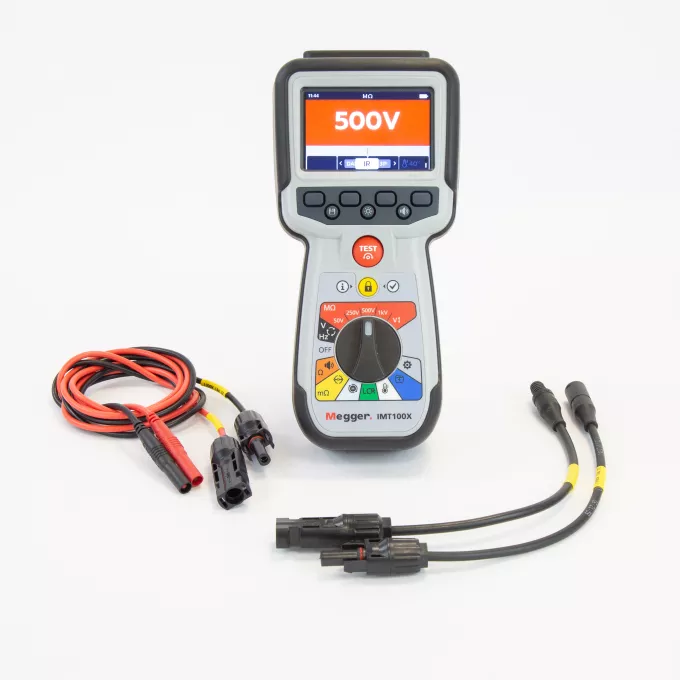
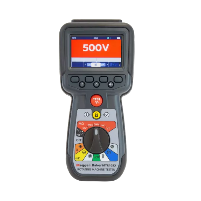
EVT100 Electric vehicle tester
Perform all routine tests on EVs and EV components with a single instrument, saving time and money.
No hidden functions or complicated menus to navigate; test with confidence from day one.
Enables traceable, auditable management of EV test results through secure live data streaming and digital reporting.
Takes the knocks and drops of tough workshop use without affecting performance or reliability.
Designed with the requirements of UNECE R100 in mind.
About the product
The EVT100 has been designed to meet the needs of those who manufacture or maintain for Hybrid and Electric Vehicles (EVs) and to aid compliance with the UNECE R100 regulations. A single compact handheld unit provides all the tests that these users will routinely need, including insulation resistance testing up to 1 kV, low-resistance bond testing, continuity and diode testing, and DC voltage measurement with polarity check.
Despite its versatility, the EVT100 is easy and safe to use, even for those with limited experience in electrical testing. It has a straightforward user interface and incorporates safety features that inhibit testing if it is not connected correctly or if an attempt is made to use it outside its operational range. Users also have access to detailed application guides and Megger’s renowned global support service.
To ensure reliable results, the EVT100 offers the option of two-, three- and four-wire low resistance testing, which can be used, for example, to verify the bonding of metal parts. The insulation resistance testing function offers automatic temperature compensation, and a guard terminal is provided to eliminate the effects of surface leakage, which could otherwise lead to inaccurate results.
To aid reporting, the EVT100 has internal storage for 256 test results. These can be easily downloaded via a standard USB memory stick and transferred to a computer for incorporation into reports and certificates. This not only saves time but also eliminates the risk of errors.
The EVT100 features rugged construction, ensuring a long, reliable operating life even in tough workshop conditions. It provides a comprehensive, reliable and easy-to-use solution for all EV and EV component testing requirements.
Connected EV testing with CertSuite Asset (EVT100X)
The EVT100X extends the EVT100 by adding Bluetooth Low Energy (BLE) connectivity, allowing test results to be managed and streamed live to CertSuite Asset on a mobile device or web browser.
This connected workflow supports traceable and auditable EV testing by linking results directly to vehicles, components, or test stages. Results can be reviewed in real time, securely stored, and retrieved later to support documentation, certification, and compliance with UNECE R100 and internal quality procedures.
The EVT100X continues to function fully as a standalone instrument, with CertSuite Asset providing an optional digital layer for users who require clearer audit trails and more efficient reporting.
- Live streaming of test results during EV testing
- Store results against vehicles, components, or assemblies
- Maintain clear, traceable test records for compliance
- Access results via CertSuite mobile app or web account
- Secure, cable-free Bluetooth communication
CertSuite Asset Lite comes as standard at no extra cost. For users that require cloud storage and Multi User Account Usage it is possible to upgrade to the full version.
Bluetooth connectivity and CertSuite Asset integration are available on the EVT100X only. The standard EVT100 operates as a standalone instrument.
FAQ / Frequently Asked Questions
The EVT100 is a unique instrument that meets the UN EEC R100 Regulation for Electric Vehicle testing. As such it allows manufacturers, workshops, and service centres to test crucial components safely and reliably in electric vehicles from HEV, PHEV, BEV and FCEV. – Hybrid, Battery or Fuel Cell run vehicles.
DC voltage measurements with polarity, continuity, resistance, insulation with leakage current detection using the guard terminal, temperature readings in live components, and temperature correction in resistance and insulation measurements.
Yes, most vehicle manufactures define customed testing values to suit their insulation safety controls. The Insulation resistance tests can be carried out at predefined values from 50 V, 250 V, 500 V and 1 kV, and user-selectable variable voltages can be set from as low as 10 V. A guard terminal conducts leakage currents away from the circuit being measured to reduce errors and avoid incorrect decisions.
This unique instrument combines three essential safety tests for electric vehicles in one handled instrument. It offers low resistance, continuity and insulation resistance using two, three and four- terminal methods, meeting and exceeding the testing ranges and accuracy levels required by the industry.
Not only complies with the UN Regulation UN EEC R100 for Electric Vehicle testing, but also with the safety protection conditions required by IEC61010 and EMC IEC61326.
Yes, to alert operators of dangerous test voltages, even when the batteries of a vehicle seem exhausted or disconnected, this instrument can be equipped with the voltage pole tester TPT420 and the MPU690 proving unit. This also conforms to the latest IEC/EN 61243-3 and DIN VDE 0682-401 standards.
The EVT100X includes Bluetooth connectivity for integration with CertSuite Asset reporting software. All core EV testing functions and measurement capabilities remain unchanged.
No. The instrument can be used fully as a standalone tester. CertSuite Asset is optional and enhances traceability, data management, and reporting.
Yes. CertSuite Asset Lite provides live data streaming, secure result storage, and basic reporting functionality at no additional cost. For users that require cloud storage and Multi User Account Usage it is possible to upgrade to the full version for a monthly subscription fee.
Not at this time. The EVT100X is not integrated with PowerDB. For the best workflow and a richer, more streamlined experience, we recommend using CertSuite Asset, which is designed to fully support the EVT100X and unlock all of its capabilities.
Further reading and webinars

Troubleshooting
Any warning conditions while using the EVT100 will appear on the display with an error code. Screen instructions will guide you through the troubleshooting process.
If the instrument does not behave as normal and the warning messages do not disappear, the instrument has a fault and needs to be repaired.
Full details can be found in the instrument’s user guide, or by contacting our technical support lines. Below are the main warning messages and their meanings:
• Test failure - Lost connection
The EVT100 will notify you if the connection is lost during the test. You can re-establish the connection and then restart the test after a few seconds by pressing the test button or by reconnecting to a test piece.
• Failed export
The EVT100 will notify you if the export fails. This may be because the receiving USB device is faulty, disconnected, full, or fails in some other way.
The EVT100 will return to its previous screen.
• Fuse Failure
No measurements can be carried out if a fuse fails. A message will appear each time you try to run a test.
Close the message by pressing the tick/check button and refer to the user guide.
NOTE: A fuse failure warning could indicate a very low insulation resistance. Check the lead connection and try again.
• Battery Low
The battery is too low to perform a test. Please charge the batteries or replace them to continue using the instrument safely.
• Charging Fault
This is a generic charging fault warning screen.
Turn the instrument off and disconnect the charger. Then reconnect and try again.
• Battery not chargeable
The battery settings are not correct to allow battery charging.
Check that the correct battery type is in the instrument.
Check that the battery settings are for NiHM.
In either case, refer to the user guide for more information.
• Battery Charging Warning
Only NiHM battery cells are rechargeable. Do not attempt to recharge alkaline or lithium cells since that is a high-potential fire hazard.
If charging the EVT100 while the instrument is turned off, an animated battery will display across the screen to show charging is taking place. Once the battery is fully charged the screen will display a solid green battery.
• Code 1000 or higher
Follow the instructions on the screen, which will suggest rebooting the instrument. If the problem persists, contact Megger.
• The screen displays a “Voltage Detected” warning during a test.
Even if you don’t expect it, a voltage can be present or can develop during a test. The instrument will inhibit a test when the voltage detected exceeds dangerous limits, and will stop the test. This voltage threshold can be set as a lockout voltage.
The lockout voltage is active on all test modes. It is hard-coded to activate at 20 V. The only exception is the insulation resistance tests, where the lockout voltage can be set as 20 V, 30 V, 50 V, or 75 V.
If the instrument does not behave as normal, and the warning messages do not disappear after following the screen instructions, please contact our technical support lines or an authorised Megger service centre for evaluation and repair.
The measurement board will carry out a short a pre-test voltage check before testing. You will see an overlay menu showing the present voltage measured if the lockout voltage is exceeded. The overlay will disappear if the voltage is lowered below the lockout voltage threshold. The screen will immediately display a voltage detected warning message with the value of the present voltage.
The lockout voltage is active on all test modes. It is hard-coded to Activate at 20 V. The only exception is for the insulation resistance tests, where the lockout voltage can be set in the settings as 20 V, 30 V, 50 V, or 75 V. Follow the test settings suggested in the user guide.
Temperature compensation is set to “OFF” by default. Temperature compensation is available in a selection of test range sub-modes:
• Insulation resistance
• IR tests
• Three-phase insulation and low resistance test
• Timed test
• DLRO (Low Resistance Ohmmeter)
• Uni-directional
• Bi-directional
Follow the test settings suggested in the user guide.
A continuity test can be performed with test currents of 20 mA or 200 mA in the following options:
- Uni-directional
- Three-phase continuity
- Bi-directional
Follow the test settings suggested in the user guide.
A low resistance DLRO (mΩ) test can be performed with a test current of 200 mA in the following options:
- Manual single direction test
- Auto single direction test
- Manual bi-directional test
- Auto bi-directional test
- DLRO three-phase
Follow the test settings suggested in the user guide.
The EVT100 can be used to perform tests in individual system components or in assemblies of a vehicle. Essential continuity tests and the low resistance of earthing equipotential components and testing the insulation of high voltage conductors and the integrity of its connectors. It also allows test voltages up to 1000 V in DC units and batteries, check the polarity of the voltage, and measure the temperature of the different components.
Interpreting test results
A low-resistance measurement is typically a measurement below 1 Ohm. At this level, it is important to use test instruments that will minimise errors introduced by the test lead resistance and contact resistance between the probe and the material under test.
At this level, standing voltages across the item being measured can cause thermal electromotive forces (EMF) at junctions between different metals. These can cause errors that need to be identified.
Testing conditions at the time of tests can also provide essential information. Maintain records of the temperature, humidity, altitude, and any electrical interference recorded by the instrument to allow space for further corrections in the test results.
There are different approaches to expected values on a test, with international standards suggesting best practice and expected values.
The low-resistance test is vital when detecting changes in electrical bonding and mechanical equipotential structures. That is particularly true in electric vehicles and its system components exposed to heavy vibrations, environmental conditions, and corrosive environments.
A good insulation resistance value means a relatively high resistance to current flow, as well as the ability to maintain a high resistance.
Insulation resistance is highly temperature dependent, and thus the results should be corrected to a standard temperature, usually 40º C. While temperature effects will be covered later, a good rule of thumb is that for every 10º C increase in temperature the current doubles and the resistance halves. The key to making the test valuable is consistent timekeeping, effective record keeping, and constant trending of results.
Minimum acceptance values for insulation testing and test voltages are recommended by car manufacturers and international standards bodies like IEE and ANSI.
The resistance and insulation resistance tests of a component can vary with its temperature. To use the instrument with the temperature compensation function enabled, a temperature measurement must establish the temperature of the unit under test.
The thermocouple supplied with the EVT100 is set as default for type “T”, and can also be configured for “J” and “K” types.
The temperature compensation is set to “OFF” by default, and is available in a selection of test range sub-modes:
- Insulation resistance
- IR tests
- Three-phase Insulation and low resistance test
- Timed test
- DLRO (Low Resistance Ohmmeter)
- Uni-directional
- Bi-directional
Diagnostic insulation tests electrically stimulate the insulation and measure the response. We can draw some conclusions about the condition of the insulation depending on that response.
Diagnostic insulation testing covers a very wide range of techniques:
- Spot reading test (IR)
This is the simplest of all insulation tests and the one most associated with lower voltage insulation testers. The test voltage is applied for a short, specific period of time.
Polarisation Index test (PI)
This requires only two readings followed by a simple division.IEEE standard 43-2000 (Recommended Practice for Testing Insulation Resistance for Rotating Machines) defines PI as the ratio of insulation resistance at 10 minutes divided by insulation resistance at 1 minute.
The thermal mass of the equipment being tested is usually so great that the overall cooling that takes place during the 10 minutes of the test is negligible.
In general, a low ratio indicates little change and hence poor insulation, while a high ratio indicates the opposite.
PI results >1.5 are regarded as acceptable by IEC60085:-01:1984 for thermal class rating A, and PI results >2.0 for thermal class ratings B, F and H.
Dielectric Absorption Ratio (DAR)
This measures resistance over time expressed as a ratio of resistance at time t2 divided by resistance at time t1.
The assumption is that insulation temperature does not vary widely over the duration of the test so the resulting DAR and/or PI values are temperature independent.
This test is defined as the ratio of insulation resistance at 1 minute divided by insulation resistance at 30 seconds.
In general, a low ratio indicates little change and hence poor insulation, while a high ratio indicates the opposite.
Timed insulation resistance test T(s)
A timed test will automatically terminate an insulation test after a preset time. The default timer is set to 1 minute and is adjustable in the settings function. This is a useful feature that saves you from watching the display for the full duration of the test, and the possibility of missing the 1-minute reading.
User guides and documents
Software and firmware updates
EVT100
-
Extract the zip archive to the root folder of a USB pen drive.
-
Plug the USB pen drive in to the USB slot at the top of the instrument.
-
The boot loader screen will be displayed when the instrument starts up.
-
Press [OK] to upgrade the firmware or [TEST] to cancel.
-
The update will progress through various stages.
-
When complete, remove the USB.
-
Restart the EVT100 (turn off and on).
-
The firmware update screen will display while the update is in progress.
-
The instrument will reboot after the update is complete.


