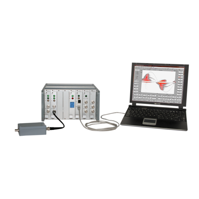
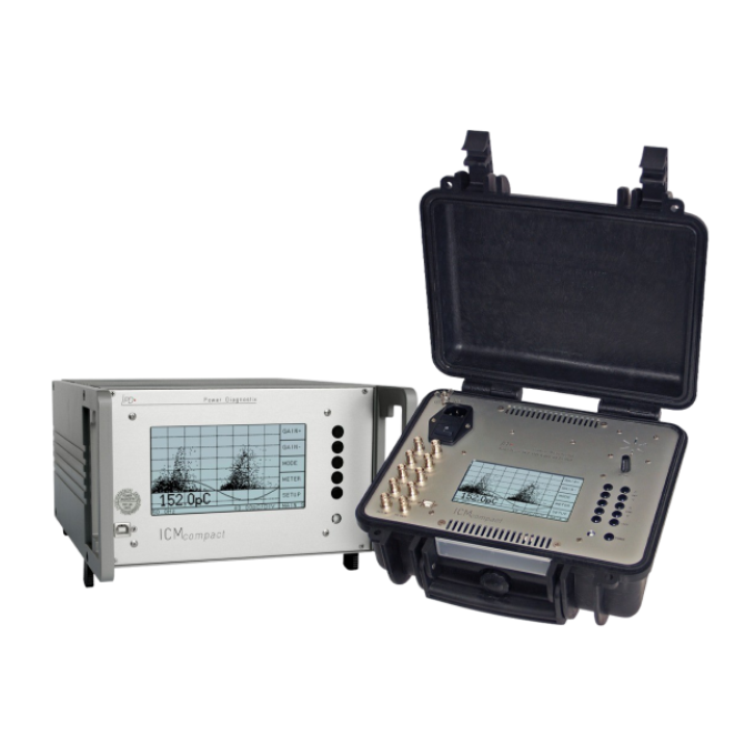
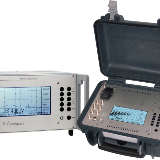
ICMflex partial discharge detector, partial discharge fault locator, and loss factor measurement system
Simplifies difficult measurement tasks
A single instrument for different high voltage assets and different measurements
Three different kinds of measurements combined in one instrument
Partial discharge (PD) detection, PD fault location on cables, and tan delta measurements can all be performed simultaneously
Minimise testing and operation time
The operation principle minimises testing as well as operation time and guarantees quick operational readiness thanks to an easy, user-friendly setup

About the product
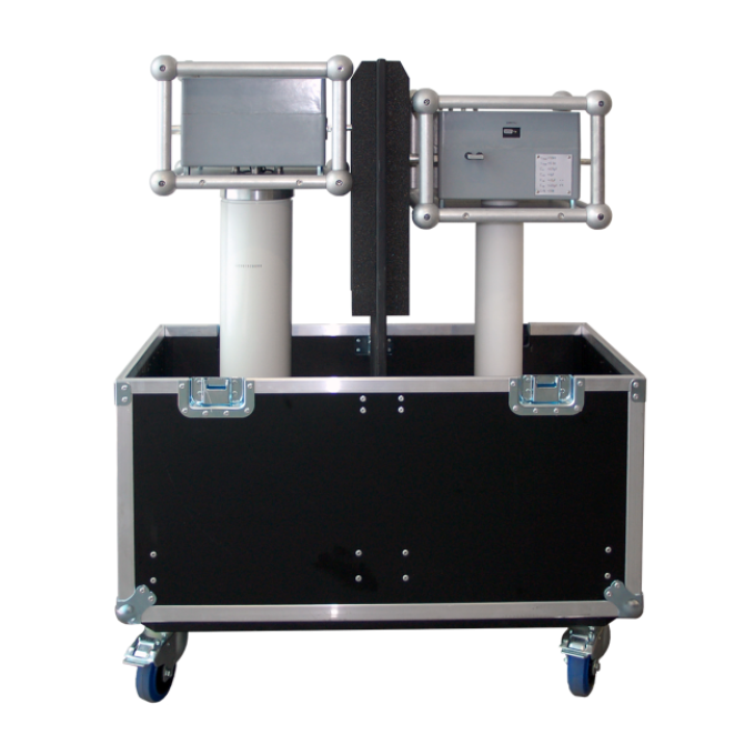
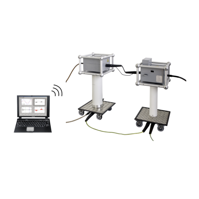
The ICMflex partial discharge (PD) detector, partial discharge fault locator, and loss factor measurement system is a versatile instrument for distribution-class cable testing and rotating machine testing, as well as other field tasks involving partial discharge detection, loss factor (tan delta) measurements, and partial discharge fault location. It has been designed to simplify testing and allows you to perform a range of different measurement tasks with one instrument.
The key features of the ICMflex are:
- Modular design that enables you to combine partial discharge detection, partial discharge fault locating, and tan delta measurements according to your specific needs.
- Can be remotely controlled with the ICMflex software via Bluetooth or fibre optic cable
- Effective noise suppression methods
- Available for many different voltage levels
- The all-in-one software panel provides a comprehensive overview of all relevant measurement data
- Software-supported step-by-step guide
FAQ / Frequently Asked Questions
PD measurements are a reliable and accurate method for determining the service life and quality of stator bars and stator windings in high voltage generators and electric motors, but up to now there is no international standard that defines acceptance levels for partial discharges during factory acceptance tests for these types of high voltage components. Where PD acceptance tests lack standardization, this is not the case for tan delta measurements thanks to IEC 600034-27-3, published by the International Electrotechnical Commission in 2015. This standard defines the acceptance criteria for form-wound stator bars with slot corona protection and a nominal voltage of 6 kV or higher. So, the accuracy and efficiency of a high -frequency off-line PD measurement complements a low -frequency tan delta measurement and, therefore, combines the best of both worlds.
The ICMflex can be used with any fixed or portable high voltage power supply, such as transformers, hi-pots, resonant test systems, motor/generator sets, and VLF systems.
Building high voltage equipment requires using insulation material. Commonly used insulation materials show losses due to resistive currents or polarization currents of dipoles. Often, the magnitude of these losses can be used as an indicator for the quality of the insulation. In the case of assessing the quality of aged insulation, increased dissipation indicates oil or paper decomposition (transformers), humidity, electro-chemical processes (water -trees in polymeric cables),or heavy partial discharge. With an ideal capacitor (C), the resistance of the insulation material (dielectric) is infinitely large. When an AC voltage (V) is applied, the current (IC) leads the voltage by exactly ϕ = 90 °. A component close to this ideal capacitor with a negligible resistance should be used as standard (or reference) capacitor for the reference branch of a dielectric loss analyzer. Technical insulation systems are usually built of less than perfect insulation material, resulting in a small current (IR) in phase to the supplied voltage (V). This current can be described by a parallel resistor (R) to an ideal capacitor (C). The phase difference between the real current (I) and the ideal current (IC) can be described as phase angle: ‘deltaδ’. Because P = Q · tan deltaδ, the losses, which are proportional to tan deltaδ, will usually be given as a value of tan deltaδ to express the quality of an insulation material. Therefore, the angle ‘delta’δ is described as ‘loss angle’ and tan deltaδ as ‘loss factor’. With a good insulation of low-loss capacitors (tan deltaδ ~ 0° and ϕphi ~90 °), the ideal current (IC) is approximately equal to the real current (I); resulting in a negligible deviation of the values tan deltaδ and cos phiϕ. In Europe, the dissipation factor tan delta is mostly used to describe the dielectric losses, while in North America the power factor (PF = cos phiϕ) is commonly used. The software of the ICMflex displays both values, together with the calculated capacitance, the voltages, and the frequency.
Further reading and webinars
Related products
Troubleshooting
Check if you have the necessary user rights for installation. This requires administrator rights.
If no communication between the ICMflex and the software can be established, please reboot the control computer and check:
- If all necessary drivers are installed properly (see user guide sections 4.2 and 4.3)
- If the battery is charged.
In order to check this, measure the DC voltage when trying to establish a connection to the ICMflex. Connect the battery to the ICMflex as shown in Figure 105 in the user guide (please check the polarity first). If the voltage is 10.5 V or less, the battery needs to be recharged. If the voltage drops down even after charging for at least six hours, the battery is faulty.
On PCs running Windows 10 with the 2017 Creator’s Update, the ICMflex application window may appear very small on high resolution monitors. To enlarge the display size of the software, please take the following steps:
- Right-click on the application shortcut on the desktop.
- Choose “Properties” from the context menu, which will open the “Properties” window (Figure 106 in the user guide).
- Enable “Override high DPI scaling behaviour” and set “‘Scaling performed by”’ to “System” on the “Compatibility” tab.
- If you have administrator rights, you can change the settings for all users by clicking the corresponding button.
- Approve the change by cl
Interpreting test results
The evaluation of a PRPD pattern, enables you to determine the kind of fault within the test object. Most partial discharge faults such as insulation damages, voids, surface discharges, or floating points will have completely different partial discharge pattern. Typical criteria to classify these patterns are:
- Phase position of the maximum partial discharge
- Phase position of the starting electron
- The gradient of discharges
- The shape of discharges in the positive and negative half-cycle
- The absolute value of discharge in pC or nC
- Short-time or continuous discharges
For successful interpretation, it is also necessary to get as much information as possible about the test object and its environment. Such information can be, for example, temperature, installation condition, age of the test object, previous faults, or weather conditions. It is useful to store typical PD patterns of known faults in an archive, which can be done by using Power Diagnostix’s ICMflex software. This customer-specific database will be helpful for later evaluation on other test objects.
User guides and documents
FAQ / Frequently Asked Questions
Power Diagnostix recommends that you calibrate the voltage measurement of the ICMflex annual for frequently used equipment to ensure accurate voltage readings and measurements. In case of any indication of erroneous voltage readings during the tests, please send the instrument to Power Diagnostix for a general check-up of the unit and a verification of the calibrated reference and shunt capacitors.
Depending on the level, nature, and source of the disturbing signals, the ICMflex system offers different options for noise handling. A noise level that is stable over the whole phase can be removed from the partial discharge pattern by the low level discriminator (LLD) function. In case the ICMflex is used for partial discharge measurements in an environment with high frequency (HF) disturbance, such as a frequency converter switching pulses, a corona discharge, or a thyristor firing, the use of the analogue gating function is recommended. The ICMflex is connected to a high voltage filter with a built-in current transformer, that picks up the disturbance signal. This signal is then used to reduce noise by blending out the impulse noises. If disturbances like the switching of a relay or a thyristor firing have a known source, it might be possible to create a TTL signal prior to the disturbance. An ICMflex equipped with the optional function for fibre optic (FO) gating can use this TTL signal, which is transmitted to a HV potential by a special gate signal transmitter (GST1) via a fibre optic cable, to blind out the PD measurement path.


