How best to kill an elephant (though we'd rather you didn't)

The “war of the currents”, when Westinghouse tried to convince the world that AC was the best choice for generation and transmission of power while Edison championed DC, is well known to engineers. And so is Edison’s gruesome attempt to demonstrate the dangers of AC by using it to kill an elephant, an inhumane stunt he saw fit to immortalise by recording it with his newly developed motion picture camera, the Kinetograph. The distressing footage is still accessible on YouTube, for those with an inclination to view it.
In truth, the war of the currents was never settled; nor could it be, as AC and DC each have their own virtues and shortcomings. And so it is in the realm of insulation testing where even today a very lively war of the currents is in full swing between the proponents of AC testing and those who favour DC.
Once again, the reality is that both factions are right. In some situations AC insulation testing will yield reliable results more easily, whereas in other situations, DC has the upper hand. In other words, maybe engineers should look for an alliance, rather than a war!
To see why this is, it’s first necessary to adopt a readily understandable but nevertheless representative model of a typical dielectric. A useful approach is to consider the dielectric as if it were made up of many layers. This may sound counterintuitive, especially for nominally uniform dielectrics, but consider this. Even in a uniform dielectric, faults rarely occur throughout the whole thickness of the dielectric. In fact, an incipient fault will almost certainly penetrate only a small part of the thickness of the dielectric, which is the equivalent of saying that it affects only one of many notional layers that can be considered to make up the dielectric.
The next step is to devise an equivalent circuit for each of the layers. To a good first approximation, this equivalent circuit can comprise simply a capacitor and resistor in parallel, where the capacitor represents the AC reactance of the layer and the resistor its DC (insulation) resistance. This simple approach is not a completely accurate representation of the behaviour of the dielectric because it neglects dielectric absorption, but it has been shown to be sufficiently accurate to allow an exploration of the relative merits of AC and DC insulation testing.
With this simple layer model, the generalised equivalent circuit of a dielectric made up of n notional layers looks like this:
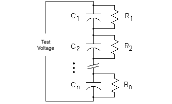
When a DC test voltage is applied from an insulation tester, the capacitive elements of the circuit will have no effect once steady state conditions have been reached. If the insulation is in good condition – which is the same as saying that the value of R for each layer is the same – it’s clear that the voltage will distribute itself evenly across all of the layers.
If there’s a defect in the insulation however, the value of R for the layer affected will be lower than that of the other layers. This means, of course, that the total insulation resistance as measured by the insulation tester will fall. If it’s a small defect, as most are in the early stages, and it only affects a thin layer of the dielectric, the change in the measured insulation resistance – which includes the contributions from the many good layers where no change in resistance has occurred – will be small.
And there’s another important factor to be considered. As the resistance of the faulty layer falls, so does the voltage that appears across it. This means that the fault is stressed less, making it even harder to see with a DC test. It’s also easy to see that increasing the test voltage does little or nothing to improve things, as the additional voltage will mostly be distributed across the good insulation layers, putting these under additional stress, with a consequent risk of further failures.
If an AC test voltage is used, the situation is rather different as the distribution of voltage across the dielectric layers is now primarily determined by their capacitive reactance XC, which is equal to 1/C, where C is the capacitor for the layer, as shown in the equivalent circuit. The capacitive reactance changes much less than the resistance when degradation of the dielectric occurs, so the voltage across the failing layer remains almost constant.
What does change significantly is power factor of the failing layer, because the resistive component of the current in the layer increases while the capacitive component alters only slightly. The resulting change in the overall power factor of the insulation – which includes the contributions of the failing and good layers – can be detected relatively easily by an AC insulation test set. Or at least this is the case in the early stages of dielectric degradation.
Those who care to work through the relatively simple – but rather tedious – mathematics, will discover that as the degradation of the dielectric progresses and the value of R in the equivalent circuit for the failing layer becomes smaller and smaller, the influence of this layer on the overall power factor of the dielectric decreases, making it more and more difficult to detect the problem with an AC test. Mathematical analysis will also reveal another limitation of power factor testing – it is relatively insensitive to defects in applications where the total capacity of the test specimen is large.
This already suggests that there may be some circumstances where DC testing will deliver more useful results than AC testing, and practical experience shows that this is indeed the case. For example, only a DC insulation test can confirm the presence of a relatively low resistance shunt path in an insulation system with parallel layers of insulation, such as the core to ground insulation of a large power transformer.
An AC test voltage is, as discussed, good for stressing localised defects, but consider this: capacitive reactance is inversely proportional to capacitance, and capacitance is proportional to the dielectric constant of the material in question. In other words, a higher dielectric constant means a smaller capacitive reactance.
In assets like transformers that incorporate both oil and paper dielectrics, the oil-impregnated paper typically has a dielectric constant of around 3.2, compared with a value of around 2.0 for the mineral oil. This means that when an insulation test is carried out with AC voltage, more of the voltage distributes across the oil than the paper, which is unfortunate because the paper has the higher dielectric strength.
And if the test voltage is increased to apply more stress to the paper, great care must be taken not to cause breakdown of the “weakest link” – the oil. This problem does not arise with DC testing, because the voltage distributes solely on the basis of resistance, with capacitive reactance making no contribution.
In fact, one of the most important considerations when evaluating the relative merits of AC and DC testing is timing – how far has the dielectric defect developed by the time the test is carried out? If the stage of development could be known prior to commencement of testing, then it would be possible to decide with a reasonable degree of certainty whether AC or DC testing would be the best choice. But of course in the real world, the stage of development of the dielectric fault is hardly ever known, so it is advisable to use the full range of test options.
When this is done it is found that, as would be expected from the foregoing discussion, DC testing is invaluable for determining the presence of low resistance faults and of extensive dielectric deterioration. However, in the early stages of localised deterioration, using an AC test voltage to perform power factor measurements is a better approach. When a localised fault progresses to become what is, in effect, a shortened layer, power factor goes back to near normal, and the best diagnostic tool is a capacitance test, again carried out using an AC test set.
And it shouldn’t be forgotten that simple DC and fixed-frequency AC tests are no longer the only options, particularly for assets like transformers that have complex dielectric systems. In such cases, dynamic frequency response (DFR) testing, which is in effect power factor testing carried out over a range of frequencies, can provide detailed information about the condition of the dielectric, which is available through a DC insulation resistance test or a traditional power factor test.
This short article is not intended to be a rigorous examination of the situations in which DC insulation testing is to be preferred over AC testing – or, indeed, vice versa – but hopefully it has shown that neither AC nor DC testing alone offers a universal solution. The battle between AC and DC can never be won, because in reality, there is no battle; the techniques are allies that complement each other and both have earned a permanent place in the power engineer’s armoury.
Just one more thing: Megger guarantees that no pachyderms were harmed in the preparation of this item, which is more than Thomas Alva Edison could say!


