Limitations with COMTRADE playback for a high magnitude fault
INTRODUCTION
It has been proven over many years that the use of COMTRADE files is a comprehensive and accurate way of carrying out relay testing. It tests the performance of the complete relay scheme, and testing is fast as there is no need to make the extensive changes to relay settings and configurations that would be needed if individual elements were tested separately. However, this technique has some limitations, and many pieces of test equipment used to play back COMTRADE files have shortcomings. Using a practical example, this article illuminates the challenges that may arise while recreating the high magnitude fault conditions for testing and validation.
CASE STUDY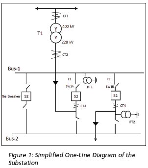
System Description
Figure 1 is a simplified one-line diagram of a 400/220 kV transmission substation where a high magnitude fault occurred. The substation has a wye-wye connected power transformer (T1) that steps down the line voltage from 400 kV to 220 kV. It also has two buses – Bus-1 and Bus-2 – which are connected with a tie breaker. In reality, there are more than two feeders but, for simplicity, the diagram shows only two – Incoming Feeder (F1) and Line Feeder (F2). Current transformers (CT3, CT4) measure the feeder currents. Voltage transformer PT1 is for bus voltage and PT2 for line/feeder voltage. CT4 has a ratio of 1000:1 (CTR) and PT2 has a ratio of 220 kV: 110 V (PTR).
Incident Description
In August 2014, the substation experienced a phase to ground close-in line fault on one of its line feeders (F2). Two different microprocessor-based distance relays with quadrilateral characteristics were being used for protection; these are designated Main-1 and Main-2 relays in this article. At the time of fault, both Main-1 and Main-2 relays tripped on Zone-1, which had no intentional operating time delay. The fault started with a phase-to-ground line disturbance and the relay picked up 33 milliseconds after the disturbance started. The problem escalated when the breaker failed to open. Unfortunately, the fault was so severe that it burned down the line conductor.
When subsequent analysis was carried out using the report generated, the fault was confirmed to be of very high magnitude. The high fault value observed in this incident is a rare occurrence, but it created concern and triggered an investigation to determine the relay’s response to the fault and to validate its reliability for similar faults in future. The fault report generated included the current waveforms shown in Figure 2.
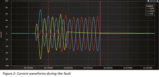
The dotted vertical red line indicates the time of relay trip operation and the vertical pink line shows the time when fault was cleared. iL1, iL2 and iE indicate Phase A current, Phase B current and ground current respectively. The incident started with a Phase B to ground fault (iL2-E) and progressed to impact Phase A as well (iL1). The maximum RMS value observed from the waveform showed the fault current for Phase B to be 55.89 A secondary, whereas Phase A had 40.1 A secondary. There was significant DC offset in the fault current that caused the waveforms to shift away from the axis. The voltage waveforms during the fault are shown in Figure 3.
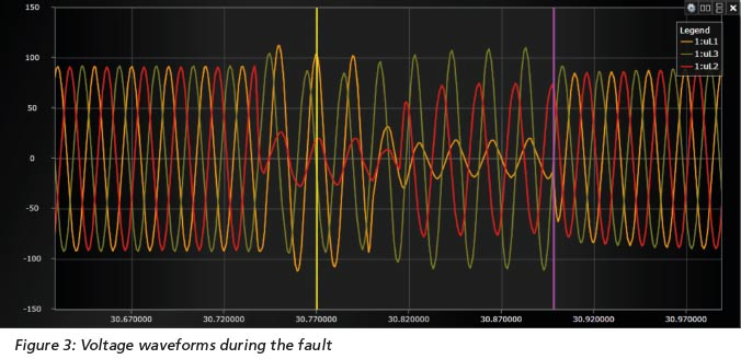
In the voltage waveforms, the yellow vertical line indicates the time of relay operation and the pink vertical line denotes fault clearing. The figure also shows some pre-fault and post-fault cycles captured by the relay. It can be seen that there was initially a collapse in Phase B voltage (uL2) and that later affected Phase A (uL1).
Utility Requirements
As a consequence of this rare high magnitude fault, the utility wanted to make sure that its systems were properly protected in the event of a similar occurrence in the future. It decided to validate the performance of the protection system by testing a relay similar to the one used in the substation where the fault occurred. COMTRADE records captured from Main-1 relay at the time of fault were used to test a similar relay (Main-2) that was normally used as a back-up. COMTRADE records were used for testing to recreate the exact currents and voltages as monitored by the main relay during the fault.
Potential Limitations
Challenges Encountered by the Utility. The Main-1 relay had the ability to capture and store relay input signals in digital form and transmit this data in another form. As the utility did not have any Digital Fault Recorders (DFRs) installed, the decision was taken to generate the event report in the form of COMTRADE file from that relay.
The retrieved COMTRADE file was replayed into Main-2 relay with the help of various three-phase relay test equipment that inject secondary three phase current/voltages. Each test equipment had its own control software that could assign the current and voltage values from the COMTRADE file to the respective current and voltage channels on the test equipment. After the files were imported into the software, it was found to be necessary to add a number of pre-fault cycles in order to polarize the Main-2 relay.
The Main-2 relay was evaluated to determine how it would perform under the same fault conditions. Because of the high magnitude of the fault, all of the test equipment available to the utility could not play back the file; the rated current output per channel was insufficient to produce currents of the required magnitude, which had to be at least 40 A. The transient playback of the fault scenario required the test equipment to generate more than 40 A on two different channels at the same time, without external parallel connections to increase the current capacity.
Potential Testing Complications
The case study also revealed some of the other problems that users may experience while testing with high fault currents using COMTRADE files. Among these are:
- Failure to generate ratios for current/potential transformers - COMTRADE records created by some relays during faults include no information on primary and secondary values for currents and voltages. As a result, the test equipment doesn’t know the correct values to inject.
- Channel conversion factor error - According to the COMTRADE standard (IEEE C37.111) the configuration file has gain factor “a”, and offset factor “b”. The channel conversion factor for a data point is (ax+b), where “x” is the stored value in the corresponding data file. Many relay test simulators fail to read the offset factor “b” at the time of import. As a result, the testing accuracy for conditions that have an offset is compromised.
- Source rating limitation - Some rare occurrences in power systems, like the
one discussed in this paper, produce very high values of fault current. To test such faults, the test equipment must have a high enough current rating to correctly replay the COMTRADE records.
The Solution
Modern test equipment that can deliver more than 40 A per channel for short periods was used to play back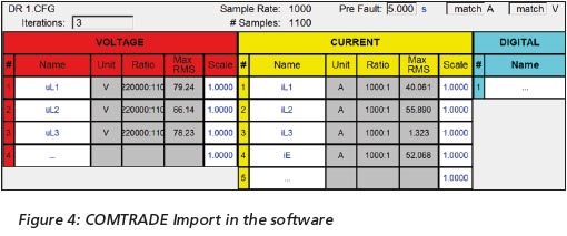 the fault. The test set had six isolated current channels and four isolated voltage channels. Using this test equipment, the COMTRADE record generated by the Main-1 relay at the time of the fault was played into the Main-2 relay, which had the same relay settings. To ensure that the software could read the configuration file and develop waveforms, it was stored in the same directory on the computer as the data file.
Figure 4 shows the software interface for playing back COMTRADE files. As seen in this figure, the software has assigned the three phase currents, three phase voltages and earth current analog channels. The software also imported accurate values from the data file. The waveform obtained is shown in Figure 5.
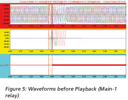
In Figure 5, the voltage waveforms are shown in the red highlighted box. Likewise, the yellow highlighted box shows the current waveforms. The Phase A line current (IL1) is red, and Phase B line current (IL2) is green. The orange vertical line indicates the time when the disturbance started and the red vertical line shows the time of relay trip. From the waveform, it can be seen that the Main-1 relay took two cycles to trip.
When the playback was carried out, it was observed that the Main-2 relay tripped for exactly the same elements as the Main-1 relay during the actual fault 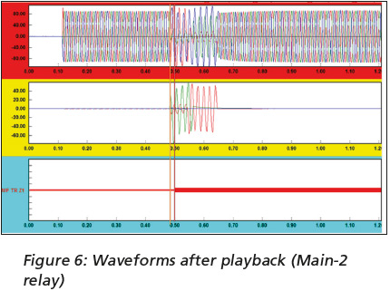 occurrence. To prove that the relay experienced the same system conditions during playback, a new COMTRADE record was generated from the Main-2 relay. The new configuration file was then compared and matched with the original file. The new waveforms developed are shown in Figure 6.
The color coding in Figure 6 above is exactly the same as that used for Figure 5. By comparing Figures 5 and 6, it is clearly evident that they share the same characteristics and values. The only difference noted was the relay operation time. Main-2 relay took only one cycle to trip its contact but Main-1 took two cycles. The indication of the trip provided the validation for a successful test. Furthermore, it also showed that Main-1 relay took more time and should not be set as the preferred source of primary protection in future.
Conclusion
The evolving requirements of the power industry have led to the development of portable digital test equipment that can not only generate high transient currents without the need for parallel connections but also accurately play back transient records. With such equipment, users can simulate power system events quickly and easily. Knowing about possible complications in the use of COMTRADE files means that users can also be well prepared for these complications and have solutions readily to hand.


