Q&A: gas-insulated switchgear (GIS)

Author: Boel Ekberg, Application Engineer
The topic for the Questions and Answers section in this edition of Electrical Tester is the testing of gas-insulated switchgear (GIS). This is a complex subject that our technical support department receives many questions about, so we asked Boel Ekberg, a support specialist who works for Megger Sweden, to draw on her experience and to provide us with some answers!
Q: I have an MV gas-insulated switchgear installation that’s never been tested because it lacks connection points on each side of the circuit breakers. Is there any way I can measure the timing of these breakers?
A: If the switchgear has a VDS (voltage detection system) interface, you can measure timing using a Megger TM1800 or TM1700 circuit breaker analyzer in conjunction with a VDS adapter. Connect the adapter to the VDS interface/outlet on the circuit breaker (Figure 1) and measure the timing by monitoring the presence of voltage in the primary circuit. The VDS outlet is a low voltage measuring point that is fed from a capacitive voltage transformer inside the switchgear, so you carry out the measurements with the circuit breaker online. No disconnections or additional ground connections are needed or possible. For additional safety, the circuit breaker analyzer can be controlled from outside the switchroom.
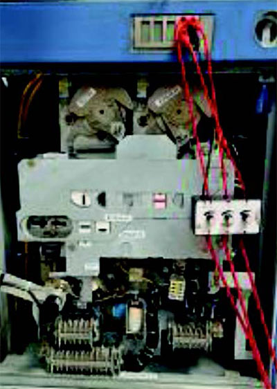
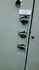
Figure 1: Switchgear with VDS adapter (left) and example VDS outlet (right)
Q: I want to measure timing on my Siemens GIS circuit breakers without disconnecting links. There are limited access points. Is this possible?
A: It will probably be possible to do this by taking advantage of the DualGround functionality offered by TM1700 and TM1800 circuit breaker analyzers. You’ll also need the accessory ferrite kit which lets you temporarily increase the impedance of the ground loop, making it easier for the instrument to achieve accurate results. Most types of GIS circuit breaker can be measured by grounding both sides and making connections at the switchgear grounding point (Figure 2). We can give you more detailed guidance if you tell us the details of your switchgear.
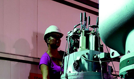
Figure 2: The author, Boel, at the connection point for DCM timing on an ABB/EXK GIS switchgear (three clamps with black handles for DualGround timing are visible)
Q: I want to make microohm static resistance measurements on my GIS. What are the things I need to consider?
A: It is possible to measure static resistance in a GIS, but you will probably have to do this with both sides grounded. You’ll need to bear in mind that you are only interested in the current that passes through the circuit breaker rather than the total current supplied by the current injector. In a GIS, the ground loop resistance is very low, so this is where most of the injected current will flow. In general, to achieve current levels through the main contact that is required by standards*, it’s recommended to have a current source of at least 300 A. With the TM1700 and TM1800 you measure the total current supplied and, with a current clamp, you also measure the current in the ground loop. Note that with some types of switchgear, it can be difficult to fit the current clamp.
* IEC minimum 50 A and ANSI/IEEE minimum 100 A
Q: I want to perform DRM (dynamic resistance measurement) tests on my GIS. What are the things I need to consider?
A: If you have suitable access points this may be possible. A common issue is that you can only access both sides of the circuit breaker by using DualGround measuring techniques and, in these cases, it is not possible to carry out DRM tests on a GIS. This is because the ground loop resistance is so low that the opening and closing of the arcing contact in parallel with it produces no measurable change in the overall resistance. The resistance of the ground loop can be less than 100 microohms, whereas the resistance of the arcing contact can be up to a couple of milliohms.
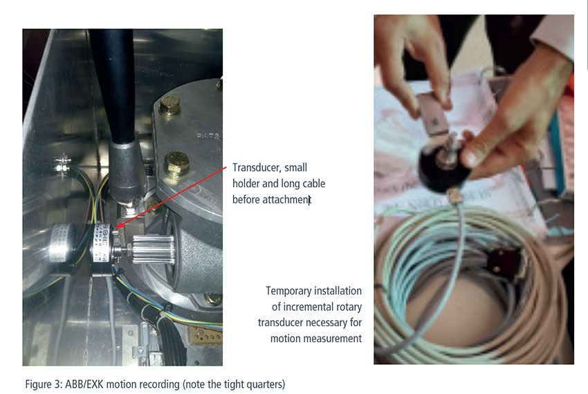
Q: I want to perform motion analysis on my GIS circuit breakers. How do I measure motion and speed?
A: The most common method is to connect a rotary transducer to the mechanism. With some ABB circuit breakers, the mechanism is in a box at the top of the breaker, whereas with some Siemens models it is at the front. A few models have built-in transducers, but this is not very common. To measure motion, you’ll need analogue or digital channels in your analyzer, a compatible transducer and a mounting set. The manufacturer of the switchgear should be able to supply the reference data for motion measurements. According to the IEC, stroke and distance should be measured directly rather than being converted. The switchgear manufacturer will be able to advise where the transducer should be attached, which is important as space is often very limited (Figure 3). Different types and sizes of transducer are available, so it should be possible to find one that fits your switchgear.