The do’s and don’ts of insulation Power Factor testing – Part 4
Jill Duplessis - Global technical marketing manager and Editor
This is the last in a series of articles about power factor (PF) and dissipation factor (DF) tests, which are widely used to assess insulation condition in transformers and other electrical assets. The first three articles, which are still available online, looked at theory, safety, general insulation knowledge and terminology. This instalment covers test preparation, choice of test voltage and analysis of results.
TEST PREPARATION
With any kind of electrical testing, careful preparation is the key to safe working and to obtaining results that are accurate and reliable. This section provides details of the preparations recommended when carrying out power factor/ dissipation factor tests, using the same do’s and don’ts format adopted in the previous articles.
Test Preparation Do’s
DO check that the transformer tank is well grounded
A poorly grounded transformer tank will often lead to very strange test results, possibly including negative values for DF/PF, and a lot of time can be wasted trying to discover what’s gone wrong.
DO physically and electrically isolate each winding’s terminals/bushings
Adequate physical isolation is essential. In particular, it is not satisfactory to rely on rubber blankets sandwiched between the bushing terminals and the busbars to provide physical isolation. Otherwise, the insulation characteristics of the rubber blanket will influence the measurement.
DO consider the consequences of leaving busbars attached to bushings
If the busbars are left physically connected to the bushings, the measured winding capacitance – Cw-g – will be greater than expected because the insulation system between the winding under test and ground can’t be measured independently; the busbar left attached to the winding introduces additional capacitance into the measurement, so the result obtained is actually Cw-g + Cbus. Also, the winding-to-ground PF/DF measurement is less meaningful as it cannot be assumed to be representative of the winding-to-ground insulation only. This is because the insulators along the attached bus frame will be included in the measurement and, since PF/DF is an average measurement, the condition of the insulation between the busbar and ground may influence the winding-to-ground power factor, making it appear better or worse than it really is. Problems in the winding-to-ground insulation will be harder to detect, as more components are included the measurement. Finally, leaving the busbars physically connected increases the possibility of results being influenced by surface leakage.
DO think about the prevailing humidity
If the relative humidity is greater than 80%, avoid testing. This is particularly important for bushings, instrument transformers and other assets that are susceptible to the effects of humidity and condensation. Note that as the surface area of the test specimen becomes larger in relation to its overall insulation size, surface leakage – and, therefore, humidity – becomes more likely to affect the measurement.
DO short-circuit each separable winding
Short-circuit each winding by connecting its terminals/bushings together, and remember to include the neutral when present. If the neutral is grounded, disconnect the ground connection for the test and reconnect it when the test is complete. Use only bare copper or aluminium wire for the shorting jumpers and make sure that all of the shorting jumpers have adequate clearances from grounded surfaces. If this is impossible to achieve, it is best, albeit undesirable, to forego short-circuiting of the winding all together. Note that because the windings must be short-circuited for testing, the turn-to-turn insulation is not stressed during PF/DF testing. For this reason, it is important to turn to other tests (like excitation current or ratio tests) to check turns insulation. The effect of failing to short-circuit the windings depends on the transformer but, in general terms, an inductive component is introduced into the measurement, which may be seen as an increase in the loss angle, with a corresponding increase in the measured PF/DF.
TEST VOLTAGE
Test Voltage Don’ts
DON’T simply accept the test voltage set by the instrument
Many instruments automatically set an industry-standard test voltage as soon as the winding ratings and details of the transformer configuration have been provided. While most of the time this test voltage will be satisfactory, keep in mind that the automatically populated test voltage is only as appropriate as the accuracy of the nameplate data entry. Therefore, it is wise to know the desired test voltage in advance and double check this with what the test software will be directing the instrument to supply before commencing with the test. Remember that the line-to-ground single-phase test voltage should not exceed the line-to-line voltage rating of the winding being energised and, for transformers with a graded insulation system, the test voltage should always be less than the voltage rating of the neutral terminal.
DON’T test oil-filled transformers in the absence of oil
Even if a very low test voltage is used, it is not a good idea to carry out (line frequency) PF/DF tests on service-aged oil-filled transformers in the absence of their insulating fluid. This is sometimes suggested as a way of assessing moisture content and predicting the success of a dry out but it’s inadvisable as the risk of fire outweighs the value of the information gained, particularly as PF/DF testing is relatively insensitive to the presence of low levels of moisture. Dielectric frequency response (DFR) testing is a better alternative.
Test Voltage Do’s
DO remember the value of power factor tip-up tests
A power factor tip-up test can be a very revealing diagnostic. With oil-paper insulation systems, PF/DF tests performed at all voltages (up to the recommended maximum) are expected to give the same value of PF/DF. With the tip-up test, an extra PF/DF measurement is made with a different test voltage, and the results compared. If this reveals that the measurements are voltage dependent, this suggests that either the insulation is degraded or that there is a problem in the test circuit. Despite its usefulness, the tip-up test is often overlooked.
DO take advantage of the smart tools provided by a (Megger PF/DF) test instrument
When tip-up testing isn’t carried out, these smart tools are particularly useful. Typically, they assess voltage dependence by looking at the harmonics generated in the dielectric response of an asset, as the level of harmonics is known to correlate with voltage dependence. If the smart tool determines that the harmonic levels are high, it warns the instrument user that further investigation, which usually takes the form of a tip-up test, is needed.
ANALYSIS OF RESULTS
Analysis Do’s
DO take into account the transformer’s history
Historical information about loading, faults, maintenance, repairs and previous test results can be a very useful aid to shaping expectations and to interpreting the most recent test results.
DO assess capacitance and total current first
If possible, refer to previous test results (reports, nameplate data, etc.) and compare the latest results with the historical data. If the winding capacitance has changed by more than ± 1% (or for C1 for bushings by more than 5 to 10%) further investigation is needed before PF/DF testing is carried out. Changes may indicate that you are not testing what you thought you were testing, or that the physical attributes of the insulation have changed notably. Without access to benchmark values, look out for abnormally low current/capacitance results. For power transformers this means less than around 1 or 2 mA for CH and CL measurements. In these cases, the culprit may be, poor grounding, substandard test connections, or an incorrectly selected test mode. Low values are not, however, necessarily a concern for CHL (and CHT) measurements, as they may simply indicate the presence of a grounded shield between the high- and low-voltage windings. Also, in some multi-winding transformers, one of the windings may itself look like a grounded shield to the test circuit – for example, CHT with an LV winding between CH and CT.
DO keep in mind general PF/DF behaviour
PF/DF reflects how efficiently the insulation is fulfilling its purpose of maintaining electrical isolation between points of different potential. With few exceptions, 0% PF/DF indicates a system with zero losses but most insulation systems in acceptable condition have inherent loss. Therefore, measured PF/DF can be “too low” – that is, lower than expected or even negative. Always remember that the key to analysing PF/DF results in practice is to look for changes from previous measurements.
DO take into account the challenges of interpreting results
Assigning significance to a change in PF/DF test results is always challenging because these are averaging tests. This means it’s impossible to know, without further investigation, whether the change is due to general, widespread contamination, ageing or a localised problem. This is important because each of these conditions needs to be treated differently. Localised problems significantly increase the risk of dielectric failure and they require immediate attention. They cannot be identified by PF/DF testing alone as they may produce only a small change in the PF/DF value because of the averaging influence of the surrounding healthy insulation. In other words, even a very small increase in PF/DF could be the manifestation of a very serious problem. In contrast, ageing of assets is to be expected and any change in PF/DF that results from the ageing process might merely be an indication that increased vigilance, in the form of more frequent testing, is desirable. PF/DF changes resulting from widespread contamination of an asset don’t necessarily need to be addressed immediately – it may be acceptable to schedule “cleaning” during the next planned maintenance period. If the contaminant is water, however, by the time it affects the PF/DF results the transformer may already have passed the point where it would have been prudent to schedule processing/drying out.
DO make sure you’re comparing apples with apples
Any observed change in PF/DF requires attention, but before you jump to hasty conclusions and spend time carrying out further tests and evaluations, make sure that you’ve eliminated the influence of “external” test variables, such as temperature, test preparation, surface leakage on the bushings and the overall condition of the bushings.
DO remember that temperature is a big deal!
All PF/DF results need to be normalized to their equivalent 20ºC values, but there’s no “universal” temperature correction curve that will suit all cases! Ageing, moisture and contamination all affect thermal response and this has led some standards bodies to recommend discontinuing the use of temperature correction curves and tables. The solution is Individual Temperature Correction , or ITC – this is correction based on the unique thermal characteristics of the asset under test, and is implemented in selected test instruments in the Megger range.
DO take into account the influence of bushings
The active insulation of high, low and tertiary bushings is included in CH, CL and CT measurements, respectively. Therefore, the condition of a winding’s bushings may influence the PF/DF results for that winding, making them appear better or worse than they really are. In either case, the condition of the materials inside the transformer tank is masked. In some cases however, the bushing insulation systems taken together may make up only a very small part of the insulation included in the CH, CL and CT measurements. In these cases, changes in the condition of the bushings do not noticeably affect the winding PF/DF measurements. Nevertheless, C1 tests should be carried out on the bushings wherever possible. When this is done, a simple calculation (provided by the test instrument’s software) is all that’s needed to subtract the bushing insulation contribution from the CH, CL and CT measurements, eliminating all uncertainty.
DO keep in mind that trending is the best way to analyse PF/DF
Trending the results of PF/DF tests for an asset over a period of time makes it much easier to see changes and to decide whether those changes are significant. And modern recording and reporting software, such as Megger’s PowerDB, makes trending easy and convenient (Figure 1 below).
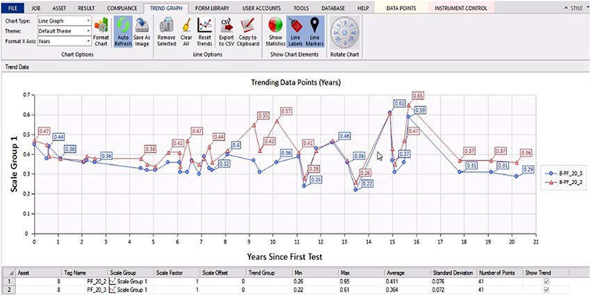
Figure 1
Analysis Don’ts
DON’T rely on general guidelines to analyse results
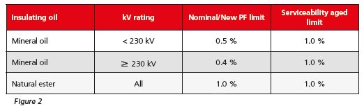
General guidelines and PF limits shouldn’t be used unless there are no previous test results available for comparison. If you have no alternative but to use them, remember that they are exactly what the name suggests – general guidelines only – so be very wary about relying on them to make important decisions. Nevertheless, a transformer that is constructed with relatively low loss materials and which has been subjected to careful handling during manufacture and assembly in the field should meet the limits in Figure 2.
DON’T panic!
When PF/DF tests give unexpected results that may potentially have serious implications, remember there are many reasons why PF/DF may have changed, and not all of them are major causes for concern. Factors that commonly produce changes in PF/DF include: HV bus not disconnected before testing; one or more HV bushings in poor or deteriorating condition; excessive surface leakage across the HV bushings due to rain, snow, etc; use of rubber blankets to achieve electrical clearances; ungrounded tank (which may produce a negative power factor measurement!); inaccurate temperature correction; moisture or other contaminants; general ageing of the asset; partial discharge; internal tracking; and an unintentional resistive path to ground.
DON'T struggle alone!
PF/DF tests are an invaluable aid to assessing the condition of insulation in transformers and other assets. Most of the time, performing these tests is straightforward, especially with the aid of the guidance provided in this series of articles and when up-to-date instruments, like those in the Megger range, are used. Even more information is readily available online in the form of articles in the TLM (transformer life management) series on the Megger website. Titles currently available include Moisture in Power Transformers, Dynamic Measurements of On-load Tap Changers, Individual Temperature Correction, Measuring Transformer Winding Resistance, Transformer Core Demagnetisation, Power Factor/Dissipation Factor and Capacitance, Electrical Testing Efficiency through Test Lead Management , Excitation Current and Oil Tan Delta (Sweep Frequency Response Analysis is available by request.). It is nevertheless still possible that there will be occasions when difficulties are encountered in executing tests or interpreting the results. In such cases, there’s no need to struggle alone – the Megger technical support service, which has unparalleled practical experience of testing in power environments, is ready to help. To access the service, simply contact your nearest Megger location.


