A guide to earth testing

Paul Swinerd - Product manager
Most electrical installations depend on earthing via earth electrodes to protect people and equipment. In these installations, regular testing of the earth resistance is essential, but most testing methods are either time consuming and inconvenient, or prone to giving inaccurate results. As Paul Swinerd explains, however, there is now a better alternative.
It’s tempting to think that checking the resistance of an earth electrode should be no more complicated than finding a second earth connection, such as a nearby water pipe, and measuring the resistance between this and the electrode under test with an ordinary ohmmeter. Unfortunately, life isn’t quite that simple.
Noise currents flowing in the earth will almost certainly produce large errors in the results obtained, and there’s no way of knowing how much of the resistance is due to the secondary earth connection and how much to the earth electrode itself. In other words, some sort of result will be obtained but, for all practical purposes, it is meaningless.
For this reason, a number of alternative methods have been devised for accurately measuring earth resistance. The simplest is to carry out a direct measurement, as described earlier, but with a purpose designed earth tester that uses an ac test current. By choosing the frequency of this current so that it is not an integer multiple of the mains supply frequency, it is possible to arrange for such an instrument to provide a high degree of noise rejection.
The results are far more meaningful than those which might be obtained with an ohmmeter, but there is still no way of confirming that they are accurate or, indeed, of separating out the contribution of the secondary earth.
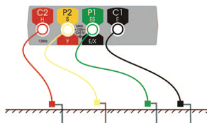
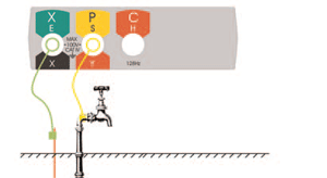
A much better method, and one which is very widely used, is usually known as the three-terminal or fall-of-potential method. This uses a connection to the electrode under test and two test spikes that must be driven into the ground before the test is carried out.
One of the spikes – the current spike – injects the test current, and should be placed as far away as possible from the electrode under test. The other spike – the voltage spike – is then driven into the ground at a number of locations, preferably in a straight line, between the current spike and the electrode. At each location, a voltage measurement is taken. Since the current injected by the instrument is known, each of these voltage measurements can be converted, using Ohm’s law, to a resistance value. In practice, this conversion is performed by the instrument itself.
If a graph is plotted of resistance versus the distance the voltage spike from the electrode under test, it should have a definite plateau region where the resistance hardly varies as the rod is moved. This value of resistance is the required earth resistance for the electrode under test.
This method is accurate, and any problems with the measurements are readily apparent, as the resistance graph will depart markedly from the expected shape. The only shortcomings are that the test is time consuming to carry out, it requires a reasonable amount of space, and that the earth electrode under test must be disconnected from all other circuits while the test is underway. These are rather significant shortcomings.
To provide a more convenient way of measuring earth resistance, the clamp-on or stakeless method was introduced. This uses a tester adapted to inject a test current into the earth electrode system via a clamp arrangement, and uses the same clamphead to measure the resulting current flowing in the electrode under test. No direct connections are required, and the earth electrode does not need to be disconnected from other circuits – indeed, for successful testing, it cannot be.
While this method is quick and easy, it has several limitations. It only works in applications where there are multiple parallel earth connections so that there is a return path for the test current, and it cannot, therefore, be used to test isolated electrodes. Since there’s no way of verifying the result, it is also unsuitable for checks on new installations where no previous test results are available for comparison, but it is good for trending of earth system condition.
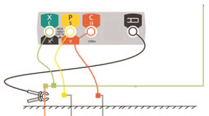
A new solution, which is more versatile than the stakeless method and more convenient than the traditional fall-of-potential method, is provided by the Attached Rod Technique (ART). In many ways, ART is similar to fall-of-potential testing, and all of the same connections are required. There is, however, one crucial difference – there is no need to disconnect the earth electrode from other circuits while the test is being carried out.
That may seem a relatively small advantage but, apart from the physical difficulty of breaking earth connections, it's important to remember that earthing is a safety function.
There are dangers in disconnecting an earth electrode as a fault current may be flowing and disconnection could give rise to a potentially lethal situation. Furthermore, if equipment is disconnected from the earth electrode to enable a test to be carried out, that equipment may no longer be safe, and dangerous situations may result.
While it may be possible to provide a temporary earth connection, or to switch off the electricity supply during the test, such measures are likely to be both inconvenient and costly.
So how does ART testing work? The key is in a current measuring clamp (ICLAMP) that is put round the earth electrode under test. The tester is designed to ignore any system leakage and noise currents that may be flowing through the earth electrode. This means that it can accurately measure the test current, in spite of extraneous influences.
With the equipment set up, the ART test proceeds in exactly the same way as an ordinary fall-of-potential test. It is still, therefore, time consuming, but there are a number of shortcuts that can be used in appropriate circumstances.
For example, instead of taking readings with the voltage spike at various distances between the electrode and the current spike, it is sometimes sufficient to take a few readings, with the voltage spike around 62% of the distance between them. This means that ART testing provides a very good balance between convenience and accuracy of results.
For earth resistance testing, it is important to have the right equipment and to understand the limitations of the various test methods – even ART testing isn't suitable in every case, although it is very versatile.
Earth resistance testing isn’t particularly complicated, but interpreting the results from the various test methods can be, which is why Megger has developed software that will do the earth testing calculations automatically, and supply a report.
The complete range of earth testers now available from Megger
4 terminal testing for soil resistivity testing
Testing soil resistivity is a fundamental part of earth system design, providing the raw data on which the design is based. Factors affecting soil resistivity include soil composition, temperature and moisture content, which can vary with the seasons. Periodic checking of the soil is necessary to ensure that seasonal variations are within the design parameters of the system. The DET4TD features 4 pole testing for soil resistivity and includes a kit of four stakes and wires.
Attached rod technique (ART)
Testing earth electrodes in existing installations using standard three pole methods normally involves the disconnection of the electrode under test to avoid the influence of parallel paths. These parallel paths are created by the earthing system of the installation or by other ground electrodes forming the ground system. Using the Megger DET3TC ground tester with the ICLAMP allows the user to measure the individual earth electrode resistance, using traditional fall of potential methods, but without disconnection of the electrode under test.
Stakeless measurement or clamp ground electrode testing
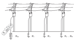
This technique is suitable for connected ground electrodes and lightning systems as it relies on an existing complete circuit with the soil to take its measurement. No disconnection is required. The DET10C or DET20C is simply placed around the conductor where it generates the signal in the circuit using magnetic induction and then calculates the resistance. They have the added benefit of being able to measure earth current. Care is needed in the application of these instruments to ensure that the circuit under test is valid.
3 terminal testing ground electrode testing
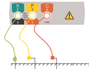
The classic methods of testing earth electrode resistance based on fall of potential are used both at installation time and also for periodic checking the condition of the electrodes. Unfortunately soils that have low resistivity are often corrosive to electrodes, making regular checking important. All the new family of Megger earth testers allow the user to perform this test and include stake and wire kits as standard.
2 terminal ground electrode testing
Use where the resistance between a conducting part, such as building steelwork and the ground electrode needs to be measured, or where site conditions means that test stakes are impractical. This test is performed using the same a.c. source as the 3 pole test method and as such may not be suitable for bonding checks as specified by local regulations. All of the new Megger earth testers can perform this test and unlike some instruments, no external linking on the instrument is required.
Megger has published a book titled ‘Getting down to earth’, a practical guide to earth resistance testing.
To get your FREE copy click here


