The high stakes of ignoring the mechanical health integrity of a transformer

Jill Duplessis
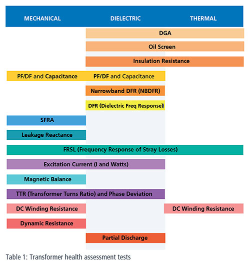
In the December 2019 issue of Electrical Tester, we looked at the history of dielectric testing of transformers and why there are so many tests currently used to assess this important aspect of transformer health (Table 1, middle column). We also mentioned thermal and mechanical indices of transformer health. While the thermal health of a transformer – its ability to dissipate heat safely and effectively – is easy to grasp, the concept of mechanical health is often shrouded in confusion. The purpose of this article is to dispel that confusion!
What is mechanical health?
The Oxford dictionary defines ‘mechanical’ in its use as a noun as “the working parts of a machine”. The definition of ‘mechanical’ as an adjective is simply “working”. Therefore, if one is interested in a machine’s mechanical integrity, one is concerned about the integrity, or the soundness in construction, of its working parts. This raises the question then, is a transformer a machine? One need not look further than the definition(s) for machine to answer this question.
The Merriam-Webster dictionary states that a ‘machine’ is:
- an assemblage of parts that transmit forces, motion, and energy one to another in a predetermined manner
- an instrument (such as a lever) designed to transmit or modify the application of power, force, or motion
By these definitions, a transformer is definitely a machine; specifically, it is a passive, electromagnetic machine. A passive component cannot introduce net energy into a circuit. Transformers ultimately allow one continuous energy path to meet the needs of its different segments. A transformer transmits nearly 100 % of energy from one segment to another and, through this process, typically modifies the associated voltage (and current) such that the two contiguous segments can simultaneously exist at different voltage levels.
A major source of confusion over the mechanical health of transformers arises from the habit of associating machines, mechanisms and working parts with movement. There’s no justification for this – working parts do not have to be moving parts. A transformer has few, if any, moving parts. When present, moving parts include tap changers, fans and pumps. It’s easy to associate the mechanical health of a transformer with these parts only, but in reality, there’s a much bigger picture to be considered.
The working or active components of a transformer include:
- The core
- Main and tap windings
- Pressed parts
- Frame and clamping structure
- Tap-changer(s)
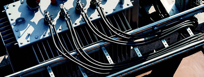
- Connecting cables
Diagnostic tests for mechanical health assessment are concerned with the soundness of construction and permanence of these active parts. Manufacturers take great care over the design, production and assembly of the active components in a transformer, but how can users confirm this soundness and how can they be sure that nothing has changed since the transformer was made? To answer these questions, we need to take a closer look at the mechanical aspects of transformers.
Mechanical aspects of transformers
The total energy of a circuit is brought into and back out of a transformer tank, with its impressively small relative footprint, for the benefit of controlling the voltage level of the energy present. We have already noted that there are few components that move intentionally in a transformer but, if it weren’t for careful design and construction, there would be many parts that might move unintentionally as a result of the forces generated within the tank. Note particularly that:
- Current-carrying components create electromagnetic fields
- The electromagnetic fields exert mechanical forces on other current-carrying components
- Current-carrying components in a transformer tank (e.g. main windings, tap winding turns, leads) are in close proximity to each other
All leads, windings, etc. therefore need to be secured so that they do not move when the transformer is energised. Why is this important?
Fundamentally, the mechanical health of the windings and leads relates to their ability to carry current. It is relatively easy to see that this ability would be compromised, for example, in the case of a mechanically compromised crimp that leads to localised overheating and burning, possibly resulting in a complete open circuit, as shown in Figure 1.
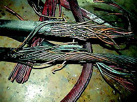
Figure 1: Open-circuited lead
However, any form of mechanical change may affect the current-carrying ability of a winding or lead. Examples include:
- Transformer core damage (Figure 2), which may affect the ability for flux to build, subsequent magnetic induction and, ultimately, current flow in windings.
- Deformation of a coil (Figure 3), particularly if these involve short-circuit or open-circuit conditions, resulting from excessive mechanical force, such as caused from a short-circuit fault. In these type of cases, an additional concern is the potential collateral damage to the surrounding insulation leading to an increased risk of dielectric breakdown.
Irrespective of short-circuit or open-circuit conditions, the movement itself of a current-carrying component can ultimately change the current-carrying ability of other nearby components, causing secondary effects that mean the transformer no longer performs to specification. Let’s explain looking particularly at leakage flux and load losses, which are the unavoidable facets of a transformer carrying load.
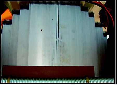
Figure 2: Transformer core damage
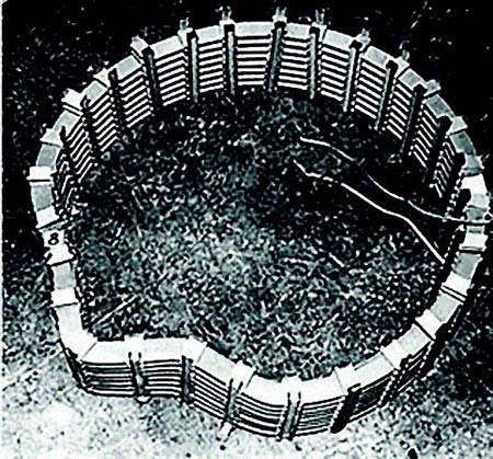
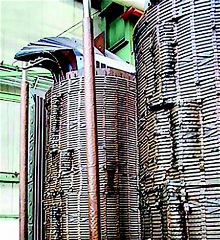
Figure 3: Winding deformation
When current flows in the windings of a transformer, leakage flux results. This is flux that does not remain confined in the transformer core for the entirety of its closed loop path. When leakage flux cuts a conductive component (such as the windings, tie plates, transformer tank, etc.), it induces a voltage, which then gives rise to circulating currents (eddy currents) within the component and produces heat (i.e. loss).
When leakage flux cuts through the primary or secondary windings and therefore induces voltage into them, it gives rise to additional eddy currents in the windings. These are known as proximity effects and they increase the eddy losses in the windings beyond those that are already present due to skin effect – another type of eddy loss that is inherently present in a conductor as soon as an AC current flows through it. If the spatial relation of the winding to core changes, more (or less) of the winding may be cut by leakage flux, thereby changing the load losses.
Proximity effects also occur when another currentcarrying conductor is brought into close proximity to the first. Unlike the skin effect, the resulting eddy currents induced in the first conductor result in non-uniform field intensity around the conductor surfaces, so current flow will not be uniform at conductor surfaces. As current is restricted to a smaller cross-sectional area of a conductor, resistance increases and current flow changes. It is worth remembering here, that mechanical health relates to the ability to carry current.
From these considerations, it is clear that the location of all components, current-carrying and non-currentcarrying, is critical and will have an effect on the operation of the transformer.
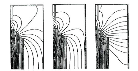
Figure 4: Electromagnetic field plots
This is because:
- The structural layout of current-carrying components (e.g. winding and leads) influences the location and intensity of electric and magnetic fields in the transformer.
- The placement and shape of non-current carrying components and shielding of the transformer tank walls influence some of the load losses due to leakage flux.
During the transformer design phase, seemingly small design adjustments in non-current-carrying conductive components exposed to fields can notably improve load loss levels, but if mechanical damage means that the leakage flux paths change, this design work is undone and these benefits are lost.
Electromagnetic field plots (Figure 4), which map out field intensities and locations relative to components, are used at the design stage to verify that localised heating will not occur with the chosen arrangement of components. Zero movement of components, in spite of the mechanical forces present when the transformer is energised, is a key design and construction objective as the movement of any internal, current-carrying component may change the resulting fields and invalidate guaranteed design behaviour. Load losses may increase, and changes in the electric field(s) may also raise concerns about the adequacy of the surrounding insulation system.
The transformer’s structural supports and clamping system are also non-trivial components. Particularly during overcurrent events, such as a through fault, these components have a key role to play in preventing the failure of the transformer. Although a transformer is designed to handle large mechanical forces, design limits may be exceeded during electrical faults. The radial mechanical forces exerted on a transformer during a fault can be upwards of tens of millions of newtonmeters (Nm), with axial forces near to one million Nm. Accordingly, the integrity of structural supports and the clamping system need to be validated. The vibrations of a winding that results from a loose or, worse, broken clamp (Figure 5) can quickly destroy the insulation between the turns.
Excessive mechanical impact, which may, for example, occur during the transportation of a transformer or as the result of an earthquake, can also create forces that exceed the transformer’s design limits. It is also important to note that the strength of mechanical components decreases as a transformer ages. This reduces its capacity for handling high stresses and forces, increasing the risk of mechanical and insulation problems.
Failure to detect mechanical faults may mean that the transformer is left in a compromised condition whereby the next time that forces occur due to a current surge, it may result in immediate failure. Alternatively, undetected faults may progress to dielectric or thermal breakdown, leading once again to the loss of the transformer.
Mechanical health assessment tests
Table 1 reveals that there are a number of electrical tests available for assessing the mechanical health of a transformer. While there are some overlaps in the diagnostic capabilities of some of these tests, each delivers advantages. Figure 6 shows the mechanical health assessment tests again, this time ordered to reflect the following summary statements about their use.
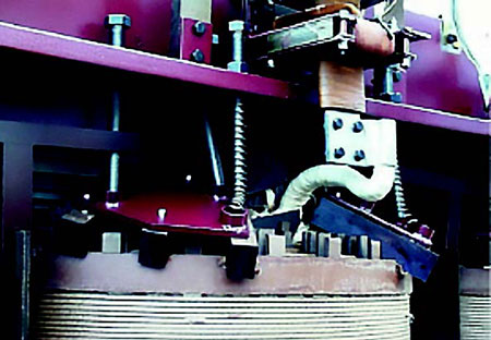
Figure 5: A broken clamping plate
One of the most important routine tests for transformers is the DC winding resistance test. This test assesses the integrity of the intended current carrying paths through a transformer (between bushing terminals) and screens for faults, such as open-circuited and partially open-circuited conditions, that may lead to localised heating and damage to surrounding insulation. A DC winding resistance test, therefore, can be characterised as both a mechanical health assessment tool and a dielectric preservation measure that can extend the life of a transformer by revealing newly developing fault conditions so that they can be addressed before they progress. Modern instruments such as the Megger TRAX, MTO300 series, and MWA300 series eliminate issues that, in the past, have tended to discourage regular measurement of DC winding resistance. One of the most significant of these is the need to saturate the transformer core before making the measurement. This used to be time consuming and difficult; it was also hard to know when saturation had been reached. Another significant issue was the difficulty of efficiently demagnetising the tranformer core after testing. Modern instruments have solved these issues, making every facet of DC resistance testing easy to manage. It is strongly recommended, therefore, that this test be routinely performed.
Some modern DC winding test instruments, including Megger’s TRAX, make provision for the measurement of dynamic resistance – that is, changes in resistance that occur as the transformer’s on-load tap change (OLTC) moves from one tap to another – at the same time as DC winding resistance tests are being performed on multiple OLTC taps. Dynamic resistance measurements do not extend the time required to perform the DC winding resistance measurements, but they do add important health assessment information about the components involved in the OLTC switching operations.
The transformer turns ratio (TTR) test assesses the health of the insulation between the turns of the windings and is, therefore, categorised as a dielectric test. Deterioration or contamination of the turn-to-turn insulation can lead to short-circuited turns, so this is also regarded as a mechanical test which, once again, relates to the ability to carry current. Current prefers the path of least resistance and divides proportionally between the resistances encountered. Therefore, short-circuited turns absolutely affect a winding’s ability to carry current. Fundamentally, a TTR test checks the central operational characteristic of a transformer – that is, does it transform voltage as expected? Knowing that it does is welcome reassurance ahead of energising the transformer. Some modern TTR test instruments also measure the phase difference between the applied voltage on the primary winding and the voltage induced in the secondary. This should be close to 0 degrees – significant deviation from this value may be an indicator of transformer core problems.
Excitation current testing introduces another extensive range of diagnostic capabilities. One of its strengths is its ability to detect partial turn-to-turn short circuits, which have not matured to a point that is detectable by other tests, as well as completely short-circuited turns. Beyond this, an excitation current test can detect a wide range of transformer core problems that may affect the ability for flux to build and subsequent magnetic induction. This test also uncovers a large number of problems in OLTCs and de-energised tap changers (DETCs). Excitation current measurements are typically made with power factor/dissipation factor (PF/DF) test instruments, making them convenient to perform routinely.
The magnetic balance test is another test that is used to assess the magnetic circuit of the transformer. One phase of the high voltage (HV), wye-connected winding is excited with a low voltage (e.g. 240 V) and the induced voltages in the other two HV windings are measured. The sum of the induced voltages should be within ± 5% of the applied voltage. This can be performed with a TTR test set, such as Megger’s newest TTRU3, or a PF/DF test instrument, such as Megger’s Delta diagnostic system, or even a multifunction test instrument, like Megger’s TRAX.
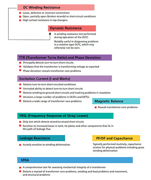
Figure 6: Mechanical health tests for transformers
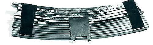
Figure 7: Strand-to-strand short-circuit
The frequency response of stray losses (FRSL) test is unique in its ability to detect strand-to-strand shortcircuits. Each turn of a transformer winding is comprised of individual strands that are insulated from one another. A strand-to-strand fault can therefore be thought of as a short-circuit within a turn, as shown in Figure 7. An FRSL test, which can be performed with instruments such as the Megger TRAX and FRAX, examines the resistive component of a short-circuit impedance test and its behaviour when the test is repeated at various frequencies up to 500 Hz. Ideally, FRSL tests are performed when the transformer is known to be in good condition to provide a baseline for reference, and then only repeated if a dissolved gas analysis (DGA) test suggests that overheating is occurring in the transformer, which may be due to a strand-to-strand fault.
A leakage reactance test is another short-circuit impedance test that is arguably the best test for detecting or confirming winding deformation as it is acutely sensitive and usually conclusive. Benchmark testing to establish a baseline is desirable, but leakage reactance test results are informative even without previous tests. Leakage reactance testing is generally performed only when winding movement or deformation is suspected.
Capacitance, which is reported in a power factor/ dissipation factor (PF/DF) test, may also detect winding deformation, but it is not nearly as sensitive as the leakage reactance test. Significant winding movements affect capacitance. In general, capacitance is sensitive to notable change in the physical attributes of a specimen under test. The advantage of capacitance measurement, however, is that, as part of routine PF/DF testing, obtaining these test results does not require additional time and effort.
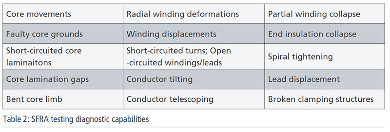 A sweep frequency response analysis (SFRA) test is an all-encompassing mechanical health assessment tool. Table 2 shows the types of problems that this test can detect. SFRA testing is frequently performed as the last or near-to-last test at the manufacturing site before the transformer is shipped to the customer and repeated when the transformer arrives at its destination to confirm that there has been no transit damage. These tests also establish a benchmark that makes it much easier to interpret future test results and to take full advantage of the extensive diagnostic capabilities of SFRA testing.
The importance of mechanical wellbeing
The primary result of a mechanical health problem is a change in the transformer’s ability to carry current, which means it can no longer meet its guaranteed design parameters. Among the consequences are:
- Higher operational costs due to the energy wasted in increased losses
- Impairment of regulation and other performance characteristics
- Reduced power handling capacity, because higher losses increase heating
- Increased risk of premature failure, because of localised heating and a resultant localised dielectric problem – unequivocally, the most serious of dielectric issues
All of these consequences are costly and disruptive, and all can be mitigated through testing, as described in this article. Testing, performed quickly and conveniently with modern test equipment, is therefore an inexpensive investment that pays big dividends.


